00197471-03_Service Manual Internal WPC5_6, EN_01-2019.pdf - 第80页
Service Manual In ternal WPC5 / WPC6 Page 3- 80 3.7.5 Sensor 8 Referenzsensor "Feed axis" Removal ➢ Loosen the two fasten ing screws (2) on the sensor. ➢ Unthread the sensor ca ble (3). ➢ Open the ferrite cor…
Service Manual Internal WPC5 / WPC6
Page 3-79
3.7.4 Sensor 7 "WPTC Present in Tower"
Spare Part
• Waffle-pack tray carrier proximity switch in memory [03057841-xx]
Preparations
➢ Remove the cover on the load unit (see 3.5.1.1 [➙ 3-33]).
➢ Dismantle the lifting magnets (see "3.5.4 Replace the Lifting Magnets" [➙ 3-40]).
Settings
➢ Check the sensor function.
➢ To do this, push a WPTC, resp. the Base Plate of the Adjustment gauge, into the tower by
hand. The sensor must switch when the waffle pack tray moves past it.
➢ Move the waffle pack tray back and forth inside the tower guidance. The sensor must switch
reliably.
➢ Move the waffle pack tray to the right and left inside the tower guidance. The sensor must
recognize the WPTC reliably. The LED on the sensor must shine continuously.
➢ The LED on the sensor will show the status:
⇨ LED shines = switched
⇨ LED does not shine = not switched.
➢ Check whether the correct output was activated.
To do this, open the station software menu Sensors
⇨ Sensors and Functions ⇨ Location ⇨ Check functions for WPC ⇨ Advanced functions ⇨
⇨ WPC I/O Ports.
The
Sensor, WPTC in tower
option must be enabled.
➢ Remove the
waffle-pack tray carrier (WPTC)
.
⇨ The corresponding LED must be off.
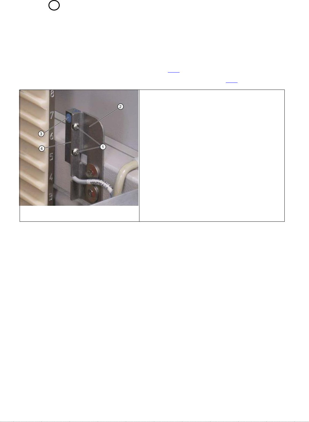
Removal / Installation
➢ Loosen the two screws (1) fastening the sensor
mounting bracket (2).
➢ Loosen the cable clamps and remove the cable ties.
➢ Unthread the connection cable as far as the control
unit back plane and unplug it from the terminal strip.
➢ Fit the sensor so that the sensor surface (4) points to
the side.
➢ Align the sensor parallel to the mounting bracket (2).
The sensor surface (3) must be aligned centrally to
the edge of the waffle-pack tray carrier. Do not
dismantle the mounting bracket.
➢ Restore the electrical connection and fix the
connection cable into place.
Service Manual Internal WPC5 / WPC6
Page 3-80
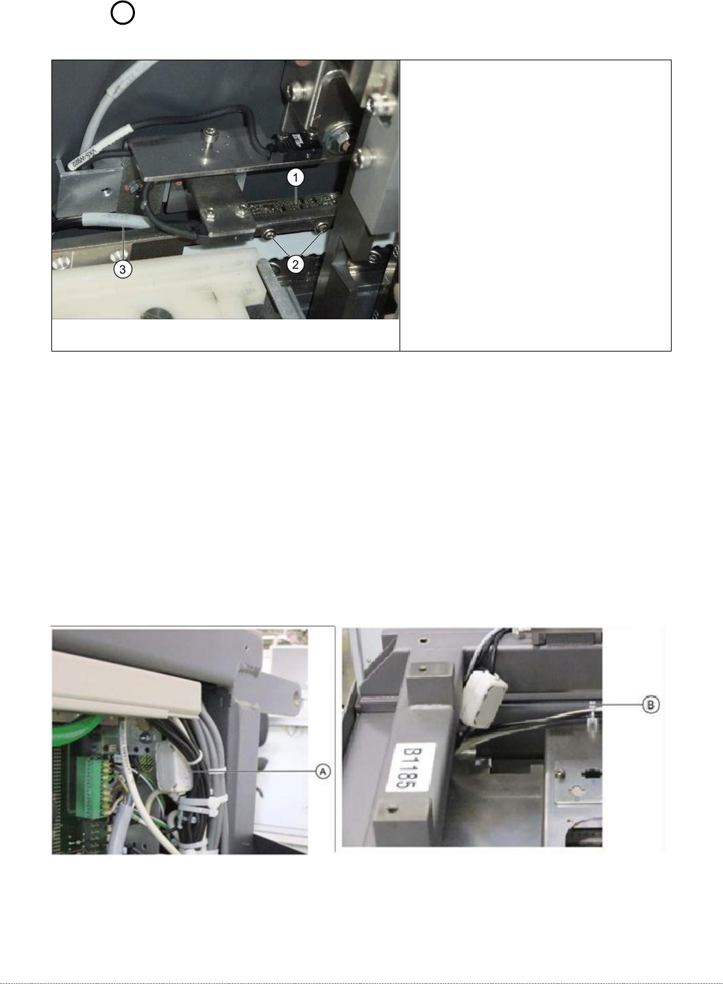
3.7.5 Sensor 8 Referenzsensor "Feed axis"
Removal
➢ Loosen the two fastening screws (2) on the sensor.
➢ Unthread the sensor cable (3).
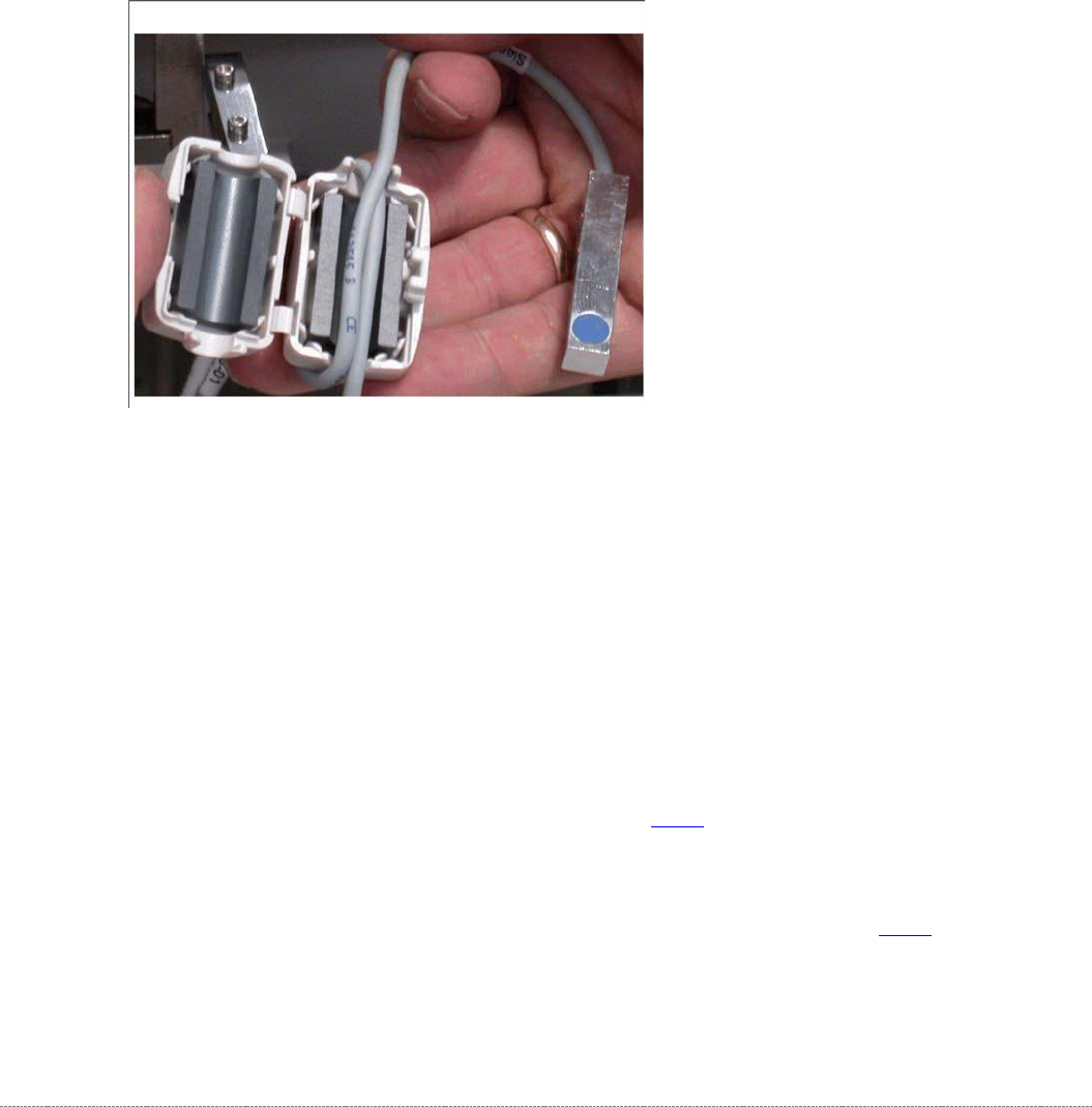
➢ Open the ferrite core (A for WPC6 or B for WPC5) at the fixtures provided, with the help of a
screwdriver.
➢ Unthread the cable clamp and remove the ferrite core. Keep these in a safe place for later
installation.
➢ Unthread the connection cable as far as the control unit back plane and unplug it from the
terminal strip.
Spare Part
• Reference point proximity switch for
feed axis [03057837-xx]
Overview
1. Reference point proximity switch for feed
axis
2. Reference sensor fastening screws
3. Sensor cable for feed axis reference
point proximity switch A = Position of the
ferrite core for WPC6 on the backplane of
the control unit B = Position of the ferrite
core for WPC5 in the load unit
Service Manual Internal WPC5 / WPC6
Page 3-81
Installation
➢ Align the reference sensor and screw to its installation point.
➢ Note the installation position. The sensor surface must point downwards and the LED
upwards.
➢ Run the connection cable.
➢ Leave a sufficiently large loop of cable, so that you can fit the cable in the ferrite core.
➢
Restore the electrical connection and fix the connection cable into place.
➢ Insert the connection cable into the ferrite core (one loop).
➢ Press the two halves together so that the fixture engages.
Settings
➢ Check the function and correct position of the reference sensor. The sensor must trigger
when the driver actuator is just below the sensor. (Reference point).
➢ To do this, open the station software menu
⇨ Sensors and Functions ⇨ Location ⇨ Check functions for WPC ⇨ Advanced functions.
➢ Enable the feed axis and click on the Reference bero button.
The feed axis will be moved so that the driver actuator triggers the reference sensor. The
reference point will be calculated.
The calculated value will be shown and can then be saved with the
Commit
button.
➢ If an error message appears, correct the mechanical position by adjusting the cam on the
driver (see "4.2.3 Reference Proximity Switch (Bero)” [➙ 4-129]) and repeat the measuring
process.
➢ Coat the cam fastening screw with locking varnish.
➢ Calibrate the reference sensor (see "4.2.3 Reference Proximity Switch (Bero)" [➙ 4-129).