00197471-03_Service Manual Internal WPC5_6, EN_01-2019.pdf - 第45页
Service Manual In ternal WPC5 / WPC6 Page 3- 45 3.6 Control Uni t and Po wer Supply Unit 3.6.1 Position On the right side of the WPC (Front side of the p ower supply) The front end of the control unit (righ t side of W…
Service Manual Internal WPC5 / WPC6
Page 3-44
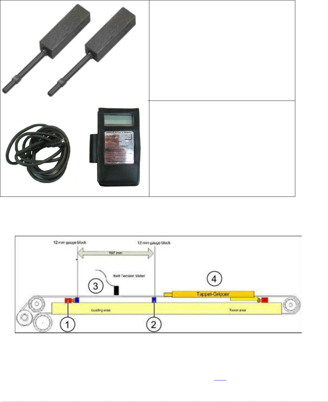
3.5.6 Setting the Load Axis Belt Tension
Tools Required
Measurement setup - measuring the belt tension for the load axis
➢ Push the two setting gauges (1 and 2) under the toothed belt, at a distance of 197 mm.
⇨ Belt tension setting value: 85 +-5Hz
➢ Tension the belt at the tensioning device with the deflection pulley (see (2) in "3.5.3
Replacing the Load Axis Drive Toothed Belt [03053795-xx]" [➙ 3-38]).
• Setting gauge small [03052363-02] 2x
• Belt tension measuring device [00326015-
xx] with instruction guide
Service Manual Internal WPC5 / WPC6
Page 3-45
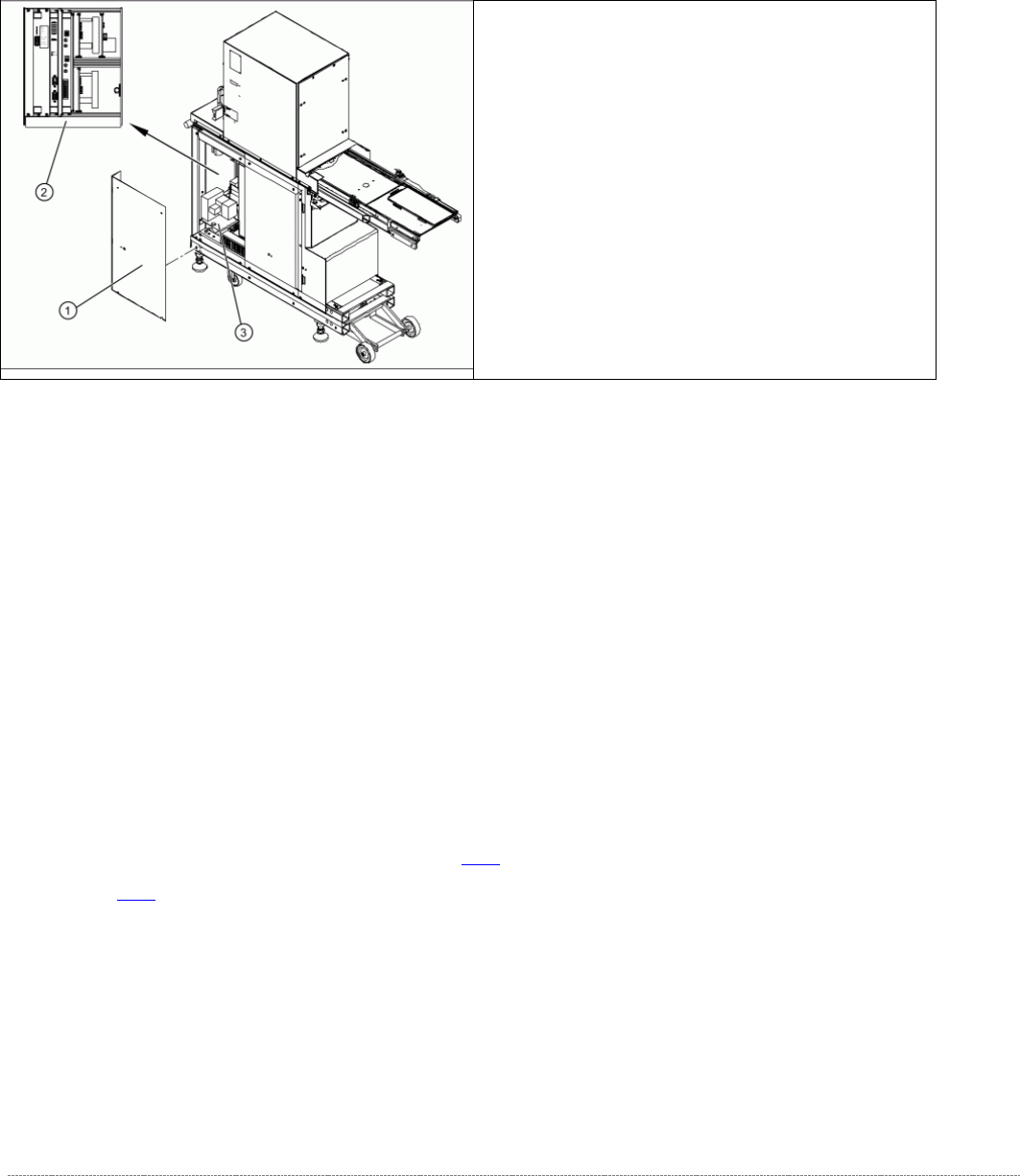
3.6 Control Unit and Power Supply Unit
3.6.1 Position
On the right side of the WPC (Front side of the power supply)
The front end of the control unit (right side of WPC) contains of:
• Servo and axis cards
• Ballast Circuit
• Power supply board
• Controller board
The front end or mounting plate of the power supply unit contains the:
• Protective contactor combination SSK – K1
• Contactors K2/K3/K5/K6
• Primary and secondary transformer fuses
For further details, see "3.6.2 Overview" [
➙
3-47] and "3.6.4 Overview of Electrical Components"
[➙ 3-60].
➢
Remove the 4 screws (1) fastening the side
covers. Underneath, you will see the front end
of the control unit (2) and the front end of the
power supply unit (3).
Service Manual Internal WPC5 / WPC6
Page 3-46
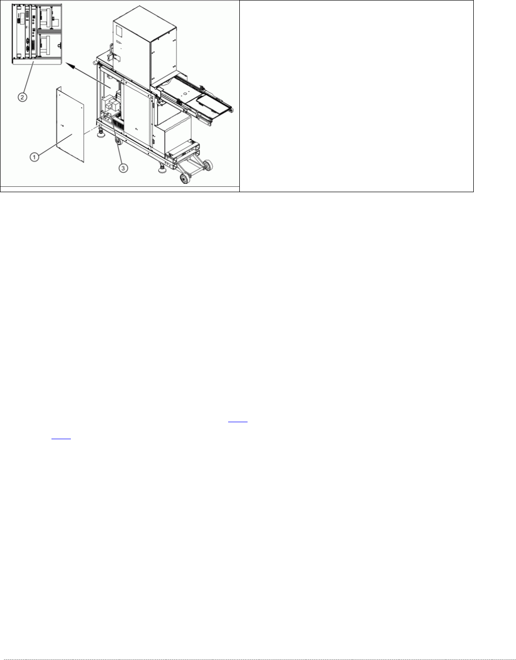
On the left side of the WPC (Backside of the power supply)
The back of the control unit contains the terminal strips and the plug-and-socket
connections of:
• The limit switches, sensors and light barriers
• The drive motors (lifting and feed axis)
• The fan connection etc.
The back part or mounting plate of the power supply contains of:
• Inrush current limitation board A2 and A1 with K4
• Line filter for 3-phase system
• Rectifier bridge
• Transformer.
For further details, see "3.6.2 Overview" [➙ 3-47] and "3.6.4 Overview of Electrical Components" [
➙ 3-60].
➢ Remove the 8 screws (1) fastening the two
side covers. Underneath, you will see the back
of the control unit (3) and the back of the
power supply unit (2).