00197471-03_Service Manual Internal WPC5_6, EN_01-2019.pdf - 第164页
Service Manual In ternal WPC5 / WPC6 Page 5-164 The positions at wh ich the strip is secured to t he to wer feature oval holes. If you need to correct t he position of the strip when s etting the 0.2 mm gap, you can re…
Service Manual Internal WPC5 / WPC6
Page 5-163
Figure 5.24: Locations of the screws securing the stopper strip to the tower housing
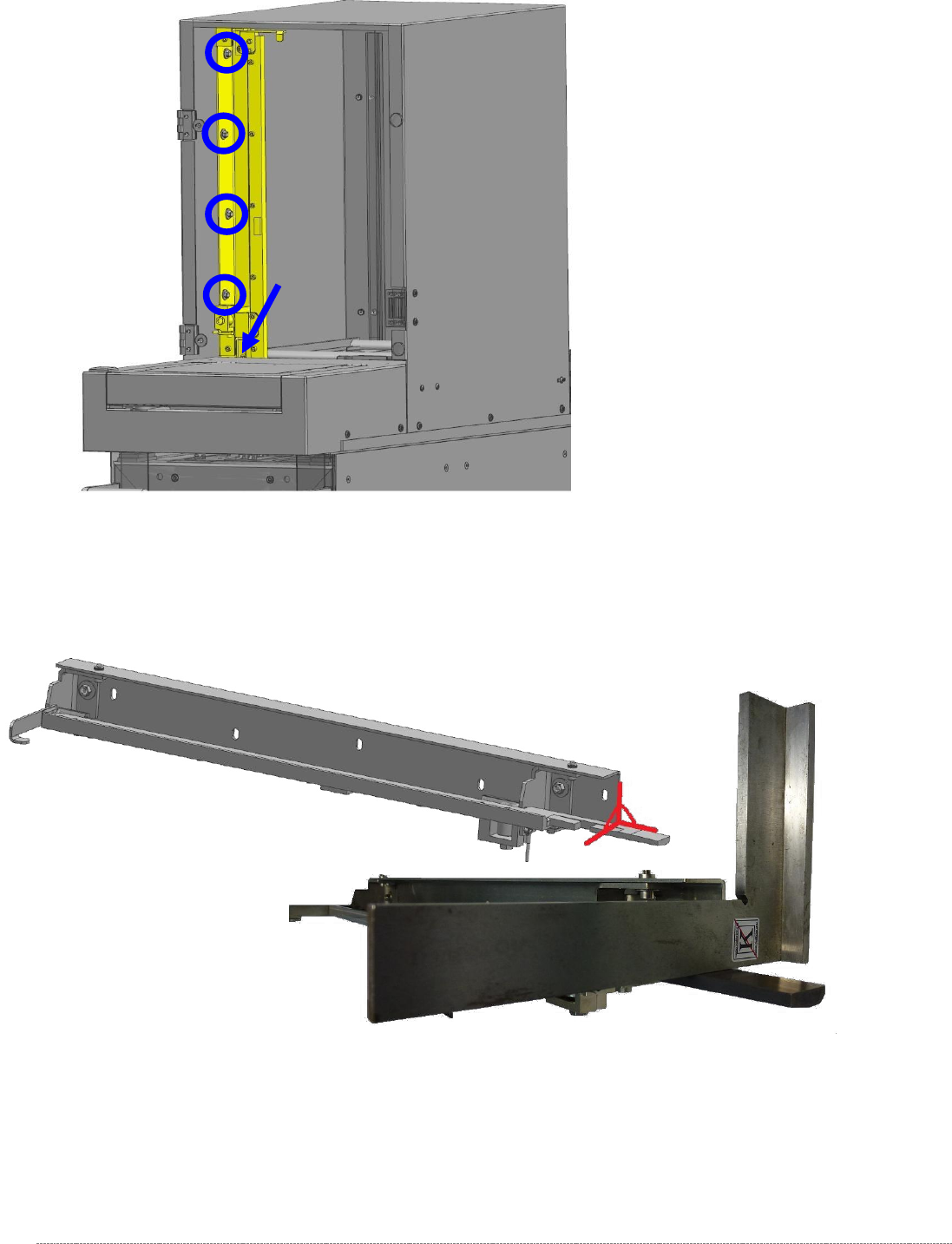
The stopper strip is secured to the tower cover using 5 screws.
Check that it is perpendicular as shown below.
Figure 5.25: Setting the stopper strip at a right angle, removed from the tower.

Service Manual Internal WPC5 / WPC6
Page 5-164
The positions at which the strip is secured to the tower feature oval holes.
If you need to correct the position of the strip when setting the 0.2 mm gap, you can release (but not
remove) the 5 nuts and move the strip horizontally.
HINWEIS / NOTICE
Using 2 gauges
If you are using 2 gauges, you can set the gaps between the guide rail and the gauges at
the top and bottom at the same time.
BOTTOM: 0.2 mm,
TOP: 0.5 mm
If you are only using one gauge, move the tower up until it almost reaches the top stopper.
Now use a feeler gauge to set a gap of 0.5 mm between the guide rail and the baseplate of the
gauge.
Service Manual Internal WPC5 / WPC6
Page 5-165
5.6 Setting the crash light barrier on the tower
The gauge is still clamped in level 5 (as described in Section 5.3).
Now attach the gauge for setting the crash light barrier to the baseplate.
Figure 5.27: Base plate of the gauge with the attachment "Strip for crash light barrier, transfer point, feed axis" [03093816-01].
Move the lifting axis to a position at which the gauge attachment interrupts the beam.
The light barrier must trigger exactly at the transition to the edge of the gauge attachment.
WARNING
Unsafe mode
You must enable "unsafe mode" in order to step the lifting axis.
You should therefore only move the lifting axis with extreme care and in small, easily
monitored steps.
Set the light barrier so that the beam is interrupted exactly at the edge of the gauge.
Figure 5.28: Trigger point on "Strip for crash light barrier, transfer point, feed axis" [03093816-01]
If necessary, move the light barrier by releasing the screw marked above on the side of the tower
cover.
Switching edge on the gauge
"Strip for crash light barrier, transfer point, feed
axis" [03093816-01]