00197471-03_Service Manual Internal WPC5_6, EN_01-2019.pdf - 第22页
Service Manual In ternal WPC5 / WPC6 Page 3- 22 ➢ Loosen the two mot or support fastening screws (3) sealed with locking varnish. ➢ Loosen (do not remove) th e tensioning screw (2) on the te nsioning device. This r ela…
Service Manual Internal WPC5 / WPC6
Page 3-21
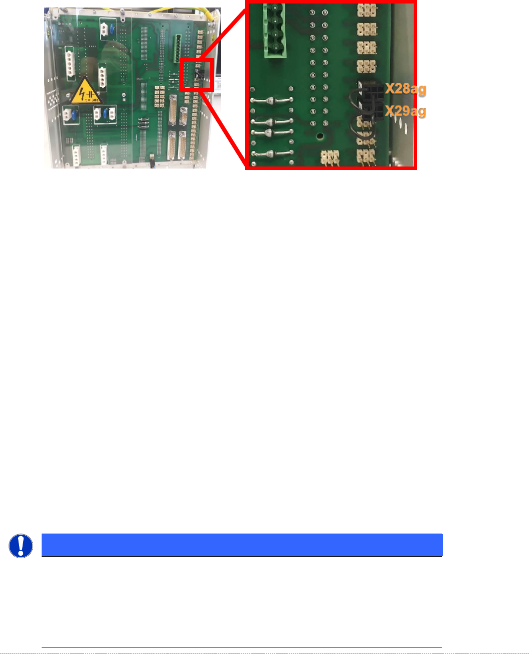
NOTE
At the rear of the control module on WPCs with new motors, a jumper must be fitted to
connector X29ag (changed motors) in addition to jumper X28ag (detection of 45 mm
component height).
Additional Information
The incompatibilities relate to the temperature sensors on the motors.
Minimum Firmware version 40A (WPCHNG_0051040A.BHX) is required to operate the new
motors in the WPC5 / WPC6.
Firmware Version 40A is available as of station software SIRIO 710.0.
If a "WPC5 900-950mm / Standard" [03067619-04], or a "WPC6 900-950mm" [03067618-04]
with new motors is to be fitted to a SIPLACE placement machine with a version of the SIRIO
software < 710.0, you should note the following:
- Any prompt by the station software to download the WPC firmware must be ignored.
- The station software must be upgraded to a version ≥ 710.0.
- If an earlier version of the WPC firmware is (inadvertently) downloaded, the WPC stops and
a temperature error message is issued.
Removal / Installation
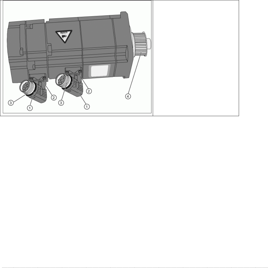
➢ Unscrew the electrical connections (7).
⇨
X1 orange cable = power cable
⇨
X2 green cable = control cable
NOTICE
Screw joints difficult to loosen
Each screw joint has an O-ring seal. This can make opening the screw joint difficult.
Use a pair of water pump pliers to help you unscrew the connection.
Make sure that the O-rings do not fall out of the screw joint and that they are not damaged.
When refitting, grease the thread and the O-rings with a little Vaseline.
Service Manual Internal WPC5 / WPC6
Page 3-22
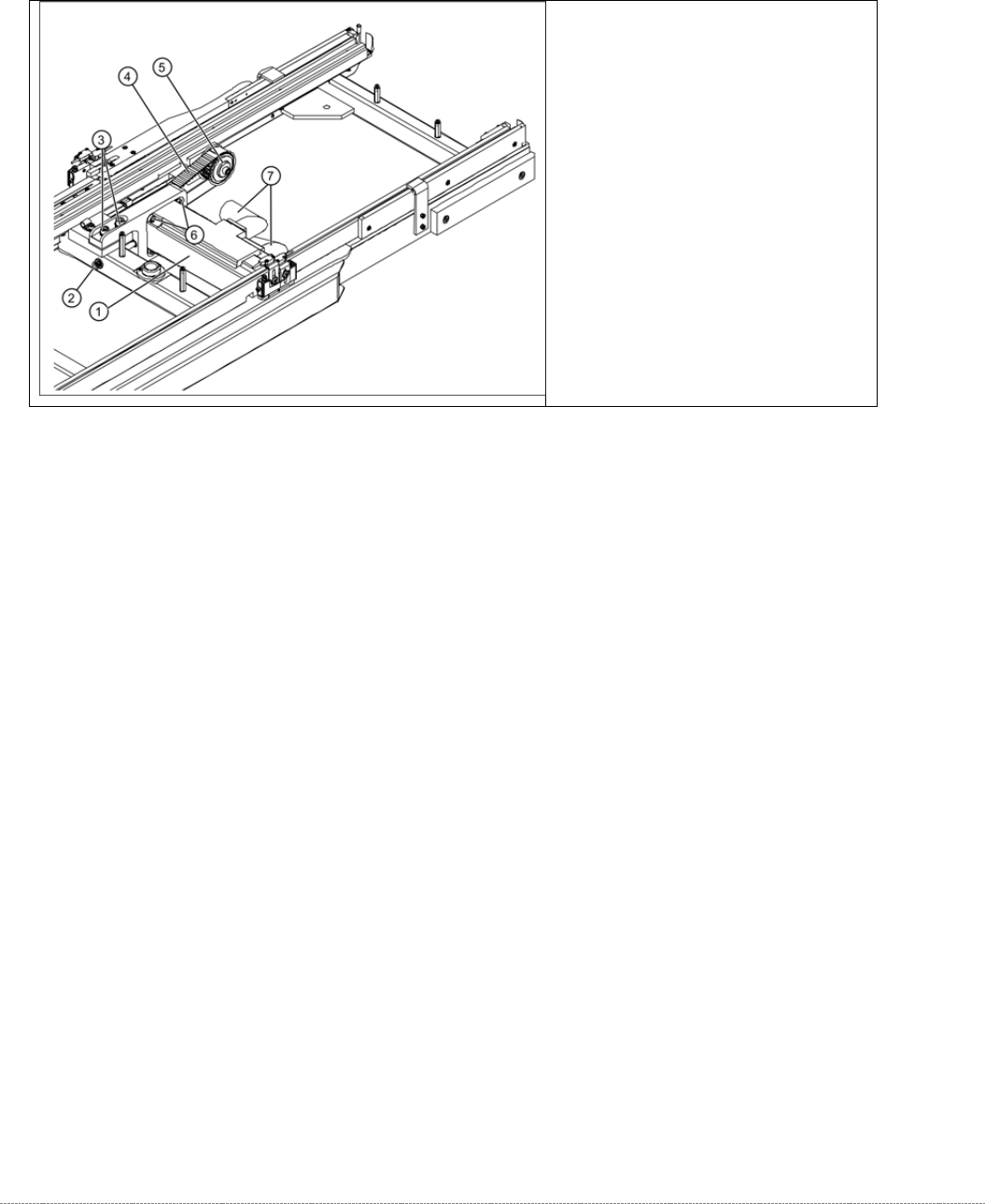
➢ Loosen the two motor support fastening screws (3) sealed with locking varnish.
➢ Loosen (do not remove) the tensioning screw (2) on the tensioning device. This relaxes the
drive toothed belt.
➢ Loosen and remove the 2 fastening screws (3) and then remove the drive motor with motor
support.
➢ Make sure that the drive toothed belt (4) is not buckled or damaged.
➢ Mark the installation position of the drive motor on the motor support.
➢ Loosen the 4 drive motor fastening screws (6) on the motor support.
➢ Fit the new drive motor with the 4 fastening screws (6) to the motor support. Observe the
original installation position.
➢ Move the motor and motor support into the installation position and run the drive toothed
belt (4) around the motor pinion and around the deflection pulley (5).
➢ Reconnect the electrical connections with the motor. When fitting, note that there is an anti-
twist lock (notch) present. Tighten the connection appropriately.
➢ Tension (pretension) the drive toothed belt at the slot provided, with the help of the motor
support. Make sure that the drive toothed belt (4) is not buckled or damaged.
➢ Loosely fix the motor support and drive motor into the installation position, with the 2
fastening screws (3).
➢ Set the final belt tension. To do this, tension the drive toothed belt at the tensioning device,
with the help of the tensioning screw (2). This moves the motor support accordingly in the
slots.
⇨ Setting value: Set the belt tension to 265 Hz +/- 5 Hz.
➢ Tighten the 2 fastening screws (3) on the motor support, check the belt tension and adjust
where necessary.
➢ Seal the 2 fastening screws (3) with locking varnish.
Overview of motor
(1) O-Ring
(2) Rotary connection
(3) Thread
(4) Motor pinion
➢ The motor connections can be
rotated by hand. Rotate the
connections to the position the
motor was installed in before.
➢
Grease the thread (3) and the O-
rings (1) with a little Vaseline.
Service Manual Internal WPC5 / WPC6
Page 3-23
3.4.3 Replace the Drive Toothed Belt
Spare Part:
• Drive toothed belt 16T5/330 [03047689-01]
Removal / Installation
➢ Loosen the two motor support fastening screws (3) sealed with locking varnish.
➢ Loosen (do not remove) the tensioning screw (2) on the tensioning device. This relaxes the
drive toothed belt (4).
➢ Loosen and remove the 2 fastening screws (3) so that you have enough play to move the
motor properly and then remove the old drive toothed belt (4).
➢ Move the motor and motor support (1) into the installation position and run the drive toothed
belt (4) around the motor pinion (2) and around the deflection pulley (5). Make sure that the
drive toothed belt (4) is not buckled or damaged.
➢ Tension (pretension) the drive toothed belt at the slot provided, with the help of the motor
support.
➢ Loosely fix the motor support and drive motor into the installation position, with the 2
fastening screws (3).
➢ Set the final belt tension. To do this, tension the drive toothed belt at the tensioning device,
with the help of the tensioning screw (2). This moves the motor support accordingly in the
slots.
⇨ Setting value: Set the belt tension to 265 Hz +/- 10 Hz.
➢ Tighten the 2 fastening screws (2) on the motor support, check the belt tension and adjust
where necessary.
➢ Seal the 2 fastening screws (3) with locking varnish.
Overview
(1) Motor Feed axis compl.
[03047364-01]
(2) Tensioning screw
(3) 2 x motor support fastening screws
(4) Toothed belt for the drive
(5) Deflection pulley