00197471-03_Service Manual Internal WPC5_6, EN_01-2019.pdf - 第140页
Service Manual In ternal WPC5 / WPC6 Page 4-140 4.3.3 Calibrating the Limit Switch The plus and m inus position of the limit switches need to b e calibrated. Calibrating the limi t switch - ➢ Select the load axis (1). …
Service Manual Internal WPC5 / WPC6
Page 4-139
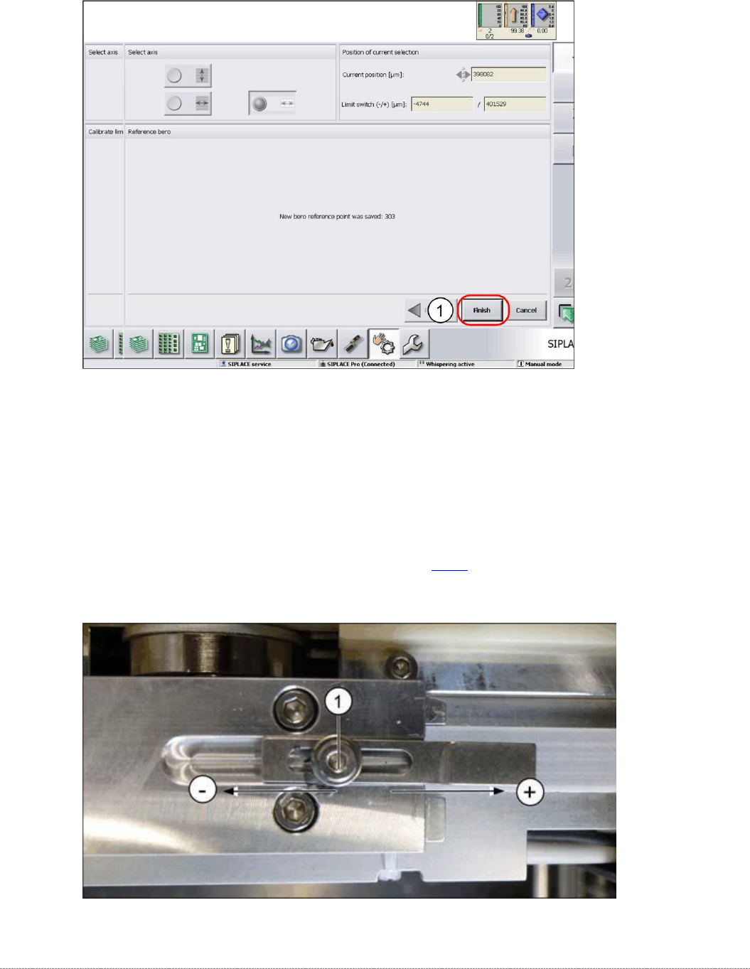
➢ Confirm the new reference point proximity switch with
Finish
(1).
Setting the Driver Cam
➢ Loosen the screw (1), fastening the cam to the driver.
➢ Correct the position of the cam by moving it accordingly in either the – or + direction.
➢ Retighten the screw (1) and repeat the measuring steps (see "3.7.13 Replacing the
Reference Point.
Proximity Switch for the Load Axis [03056947-xx]" [➙ 3-102]).
➢ Wiederholen Sie die einzelnen Schritte, bis keine Fehlermeldung mehr erscheint.
Service Manual Internal WPC5 / WPC6
Page 4-140
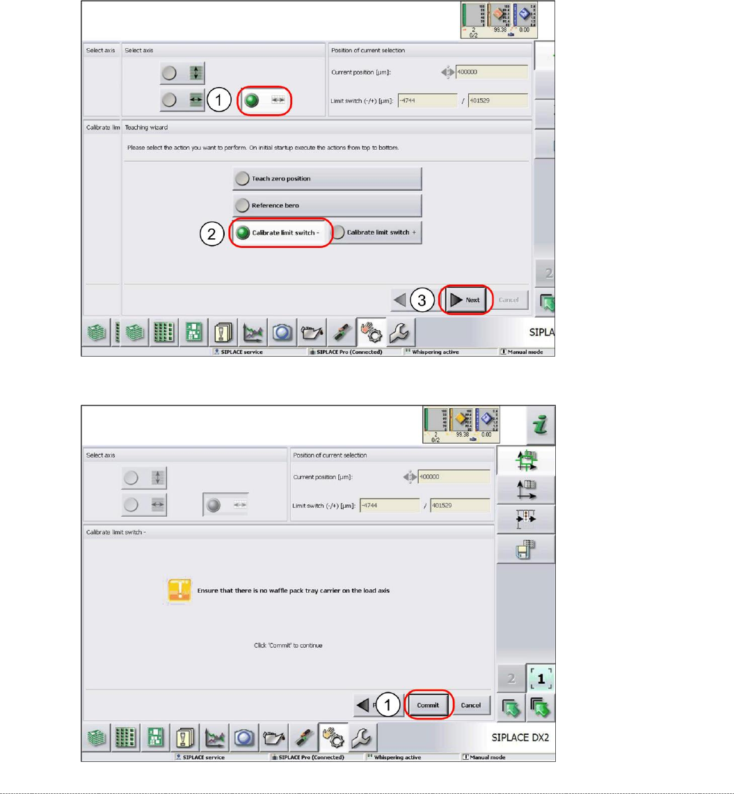
4.3.3 Calibrating the Limit Switch
The plus and minus position of the limit switches need to be calibrated.
Calibrating the limit switch -
➢ Select the load axis (1).
➢ Select the function
Calibrate limit switch -
(2).
➢ Select
Next
(3).
➢ Follow the instruction shown and continue with
Commit
(1).
Service Manual Internal WPC5 / WPC6
Page 4-141
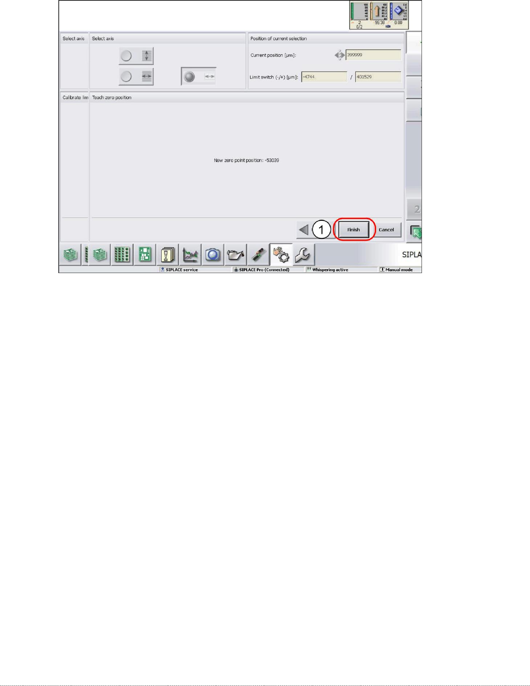
➢ Confirm the new position at which the limit switch triggers with
Finish
(1).
Calibrating the limit switch +
➢ Select the lifting axis (1).
➢ Select the function
Calibrate limit switch +
and continue with the same procedure as that
used for calibrating the limit switch.