00197471-03_Service Manual Internal WPC5_6, EN_01-2019.pdf - 第47页
Service Manual In ternal WPC5 / WPC6 Page 3- 47 3.6.2 Overview Front top - overview of se rvo amplifier and cards 1. Serv o amplifier for feed axi s (3A) 2. Ballast C ircuit 3. Brak ing resistor for lifting axis 4. Ser…
Service Manual Internal WPC5 / WPC6
Page 3-46
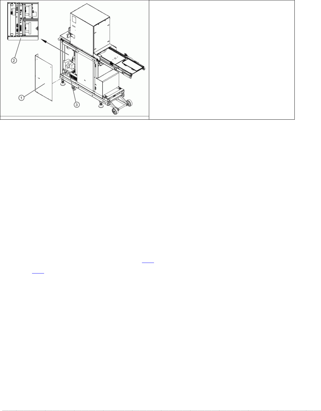
On the left side of the WPC (Backside of the power supply)
The back of the control unit contains the terminal strips and the plug-and-socket
connections of:
• The limit switches, sensors and light barriers
• The drive motors (lifting and feed axis)
• The fan connection etc.
The back part or mounting plate of the power supply contains of:
• Inrush current limitation board A2 and A1 with K4
• Line filter for 3-phase system
• Rectifier bridge
• Transformer.
For further details, see "3.6.2 Overview" [➙ 3-47] and "3.6.4 Overview of Electrical Components" [
➙ 3-60].
➢ Remove the 8 screws (1) fastening the two
side covers. Underneath, you will see the back
of the control unit (3) and the back of the
power supply unit (2).
Service Manual Internal WPC5 / WPC6
Page 3-47
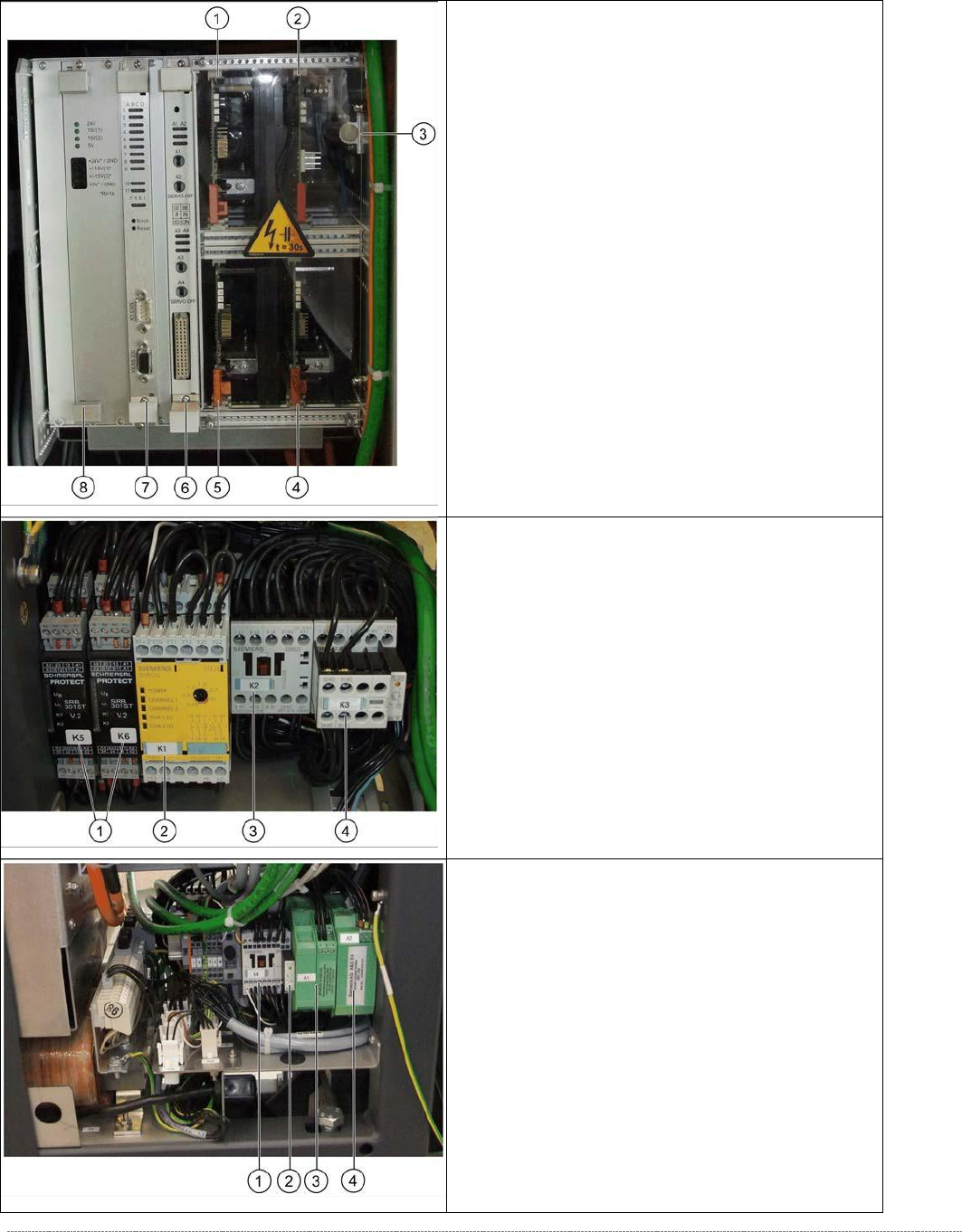
3.6.2 Overview
Front top
- overview of servo amplifier and cards
1. Servo amplifier for feed axis (3A)
2. Ballast Circuit
3. Braking resistor for lifting axis
4. Servo amplifier for load axis (WPC6 only)
5. Servo amplifier for lifting axis (10A)
6. Axis card KSP A364 analog
7.
Controller Board
8.
Supply board
From bottom
- overview of electrical unit
1. Protective door monitor and emergency STOP,
K5 and K6 (WPC6 only)
2. SSK K1
3. Contactor K 2
4. Contactor K 3
Back bottom
- overview of electrical unit
1. Contactor 3RT10 15-2BM42, K4
2. Suppression diode for contactors DC150-250V
on K4
3. Inrush current limitation board WPC
[03047752-xx] (WPC6 only)
4. Inrush current limitation board WPC NS
(WPC6 only)

Service Manual Internal WPC5 / WPC6
Page 3-48
3.6.3 Control Unit
3.6.3.1 Instructions for Working with Control Units
CAUTION
Observe the ESD regulations!
When handling control unit assemblies, observe the ESD regulations for your own safety and the
safety of the machine:
➢ When removing or installing individual assemblies, always wear the ESD wristband, to prevent
damage to the electronics system.
➢
Also observe the ESD regulations specified in the SIPLACE SX1/SX2 user manual.
3.6.3.2 Replace the Power Supply Board [03071546-xx]
Spare Part
• WPC power supply board [03071546-xx]
Removal / Installation
➢ Wear the ESD wristband.
➢ Open the top and bottom locks and loosen the 4 screws fastening the front plate of the
power supply board.
➢ Carefully pull the power supply board (see "3.6.3 Control Unit" [➙ 3-48]) out of the control
unit.
➢ Carefully insert the new power supply board.
➢ Make sure that the power supply board engages properly.
➢
Tighten the 4 screws fastening the front plate of the power supply board and lock the top
and bottom locks.
Settings
• No settings are required.
NOTICE
Check the power supply board voltages
The green LEDs on the power supply board only show whether voltage is present or not
(function monitoring). They do not show whether this voltage is correct.
Use a digital multimeter to measure the voltages at the respective pins on the front plate
of the power supply board.