00197471-03_Service Manual Internal WPC5_6, EN_01-2019.pdf - 第76页
Service Manual In ternal WPC5 / WPC6 Page 3- 76 WPC6 – Elektrics_2; Serie n-Nr .: > 3xxx
Service Manual Internal WPC5 / WPC6
Page 3-75
3.7.1.3.3 WPC6 Serien-Nr. > 3xxx:
WPC6 – Elektrics_1;
Serien-Nr.: > 3xxx
Service Manual Internal WPC5 / WPC6
Page 3-76
WPC6 – Elektrics_2;
Serien-Nr.: > 3xxx
Service Manual Internal WPC5 / WPC6
Page 3-77
3.7.2 Sensor 1 "WPTC available"
Spare Part
• Proximity switch for WPTC available sensor [03056853-xx]
Removal / Installation
➢ Loosen the 6 screws fastening the metal cover on the feed axis and then remove this cover.
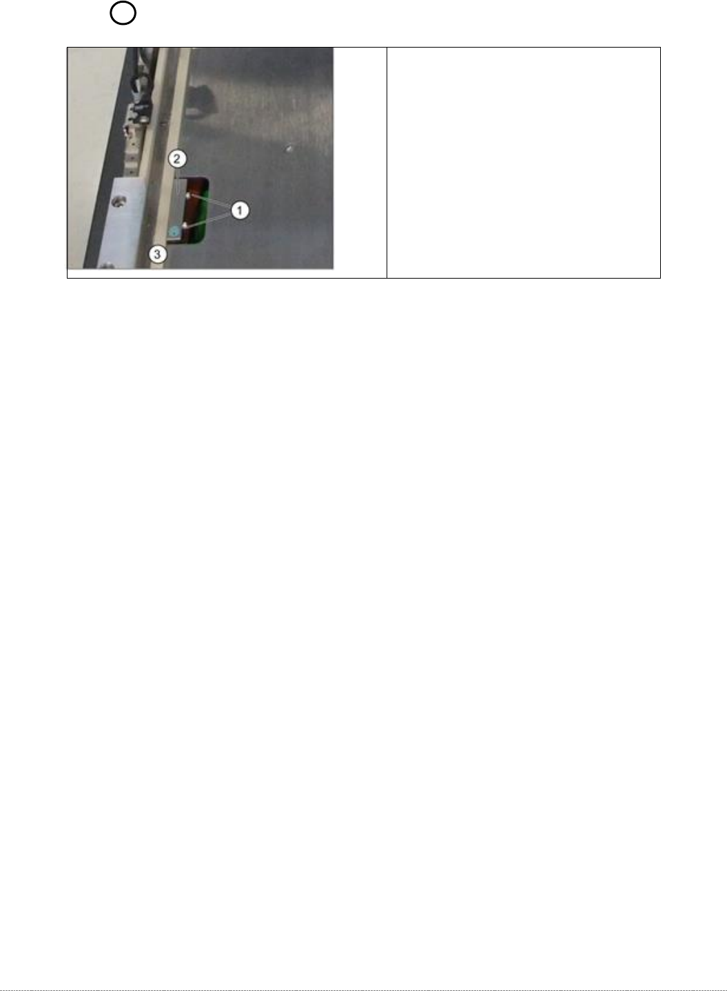
➢ Loosen the two fastening screws (1) on the sensor.
➢ Loosen the cable clamps and remove the cable ties.
➢ Unthread the connection cable as far as the control unit back plane and unplug it from the
terminal strip. The cable is run from the right-hand side, along the underside of the feed axis
to the left-hand side and from there to the back plane.
➢ Fit the sensor so that the sensor surface (2) points upwards.
➢ Align the sensor parallel to the white guidance rail (3).
➢ Restore the electrical connection and fix the connection cable into place..
Settings
➢ Check the sensor function.
➢
To do this, push a waffle pack tray carrier (WPTC) by hand over the sensor. The LED on the
underside of the sensor will show the status:
⇨ LED shines = switched
⇨ LED does not shine = not switched.
➢ Check whether the correct output was activated.
➢
Go to the station software menu
⇨ Sensors and Functions ⇨ Location ⇨ Check functions for WPC ⇨ Advanced functions ⇨ WPC I/O ports.
➢ Remove the waffle pack tray carrier.
⇨ The relevant display must be off.
1. Fastening screws
2. WPTC available sensor
3. Guidance rail