00197471-03_Service Manual Internal WPC5_6, EN_01-2019.pdf - 第85页
Service Manual In ternal WPC5 / WPC6 Page 3- 85 At WPC4 and at WPC5 / WPC6 up to serial no. 3xxx- , light barriers with normal electrical c onection are in use, which were directly connected to the WPC control unit (c …
Service Manual Internal WPC5 / WPC6
Page 3-84
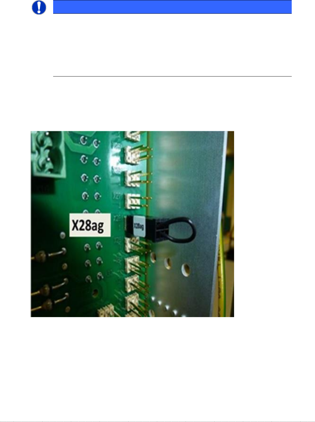
To enable the query of the third light barrier, for use on a "Very High Force TWIN-Head (VHF-
40mm/70N), a coding plug is required, which is plugged into the backplane in the control slot
on X28.
HINWEIS / NOTICE
Monitoring of the 3
rd
CO-height (very high CO’s) only with 45mm Option
The light barrier for the 3
rd
CO-height is only monitored if the coding plug, described
below, was inserted.
To avoid collisions with the sensor retainer, the 3
rd
CO level on the feed axis is set to
35mm.
At the loading axis (NSM module) this photocell is directly set to 45mm.
Service Manual Internal WPC5 / WPC6
Page 3-85
At WPC4 and at WPC5 / WPC6 up to serial no. 3xxx-, light barriers with normal electrical conection are in
use, which were directly connected to the WPC control unit (called LB type 1 in the following).
At WPC5 / WPC6 from serial no. 3xxx-, new light barierer are in use, which are using a fibre optic cable.
Those are connected to a control unit, which is finaly connected to the WPC control unit (called LB type 2 in
the following).
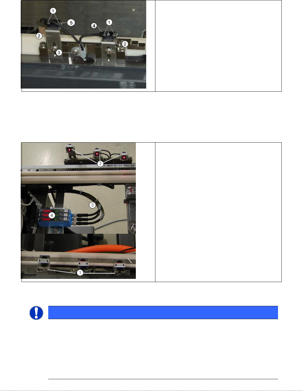
Overview
LB Type 1
1. Fixing screw for Crash light barrier.
2. Fixing angle Crash light barrier (transmitter)
3. Cable fixing Crash light barrier.
4. Crash light barrier normal height Components, with
LED
5. Crash light barrier high components, with
LED.
Overview LB Type 2
1. Fibre optic cables on holders (here Receiver).
2. Fibre optic cables on holders (here
Transmitter).
3. Cable for Crash light barrier CO heights.
4. Control units:
„Fibre opt.sensor WLL180T-M preconfig SXa“
[03093294-01]
„Fibre opt.sensor WLL180T-F preconfig SXa“
[03093295-01]
Data sheet see attachment of this document!
NOTICE
Spare Parts
At LB Type 1, transmitter and receiver are one spare part.
The transmitter and the receiver of one light barrier (different cable length depending on
height type) are delivered as one spare with one part number.
Depending on the error occurring, you may need to replace the transmitter and receiver
together.
Service Manual Internal WPC5 / WPC6
Page 3-86
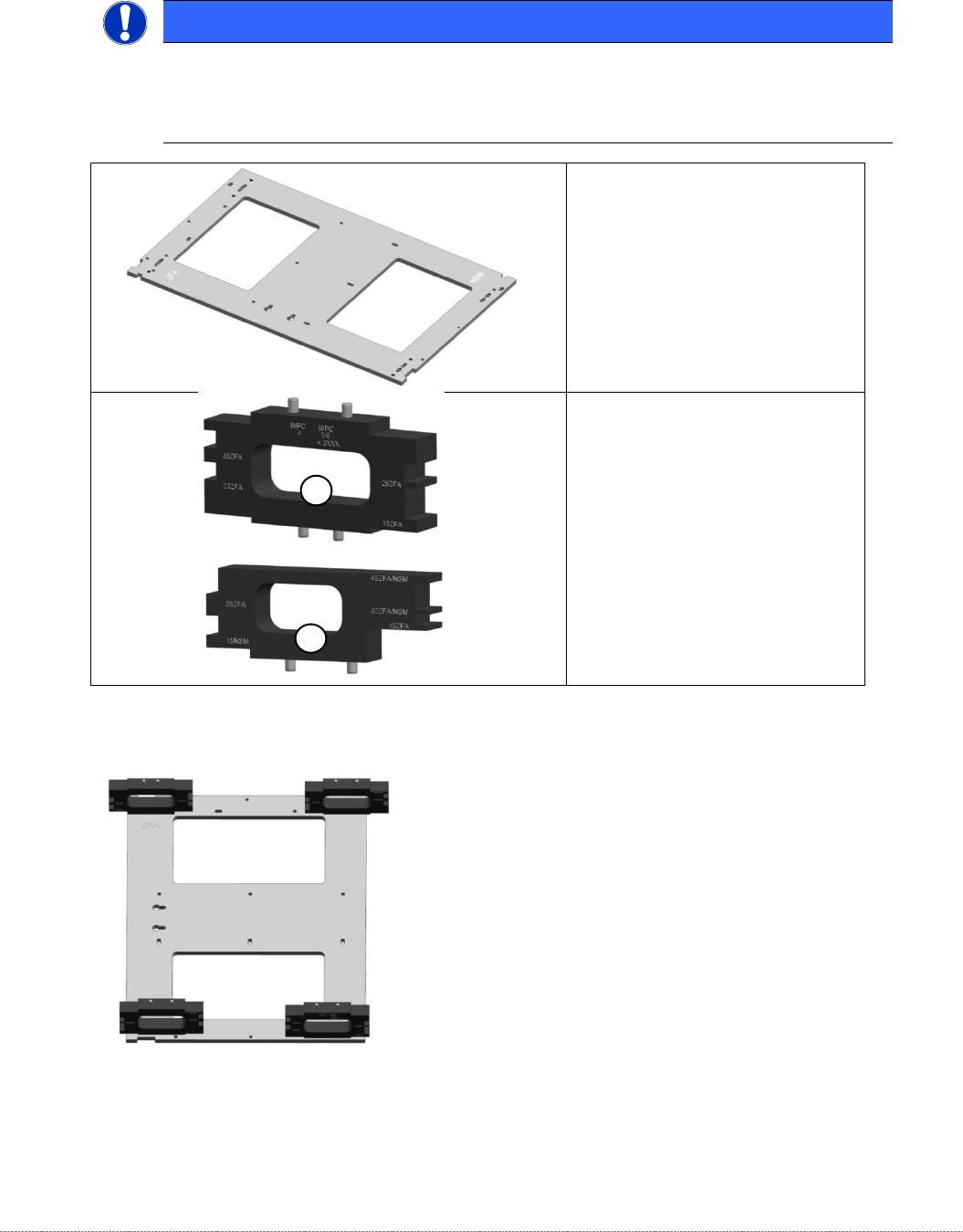
Tools / Equipment
Example:
„
Jig for WPC4-6 base plate
“
[03073064-02] with
„
mounting aid WPC 4-6 old LB
“
[03110476-xx]; the aid can be used
on 4 different positions.
NOTICE
Simplified mounting
To bring the sensor easy into the right position, you can use the „Jig for WPC4-6 base
plate“ [03073064-01], together with the corresponding Mounting aid.
•
„Jig for WPC4-6 base plate“
[ 03073064-02]
1) „Mounting aid WPC4-6 old LB“
[03110476-xx]
for all WPC4, as well as WPC5
and WPC6 up to serial no.
3xxx-
2) “Mounting aid WPC6 HC cpl.“
[03110969-xx]
for all WPC5 and WPC6 from
serial no. 3xxx-
1
2