00197471-03_Service Manual Internal WPC5_6, EN_01-2019.pdf - 第132页
Service Manual In ternal WPC5 / WPC6 Page 4-132 ➢ Confirm the new pos ition at which the limit s witch triggers with Finish (1). Calibrating the limi t switch + ➢ Select the feed axis ( 1). ➢ Select the function Calibr…
Service Manual Internal WPC5 / WPC6
Page 4-131
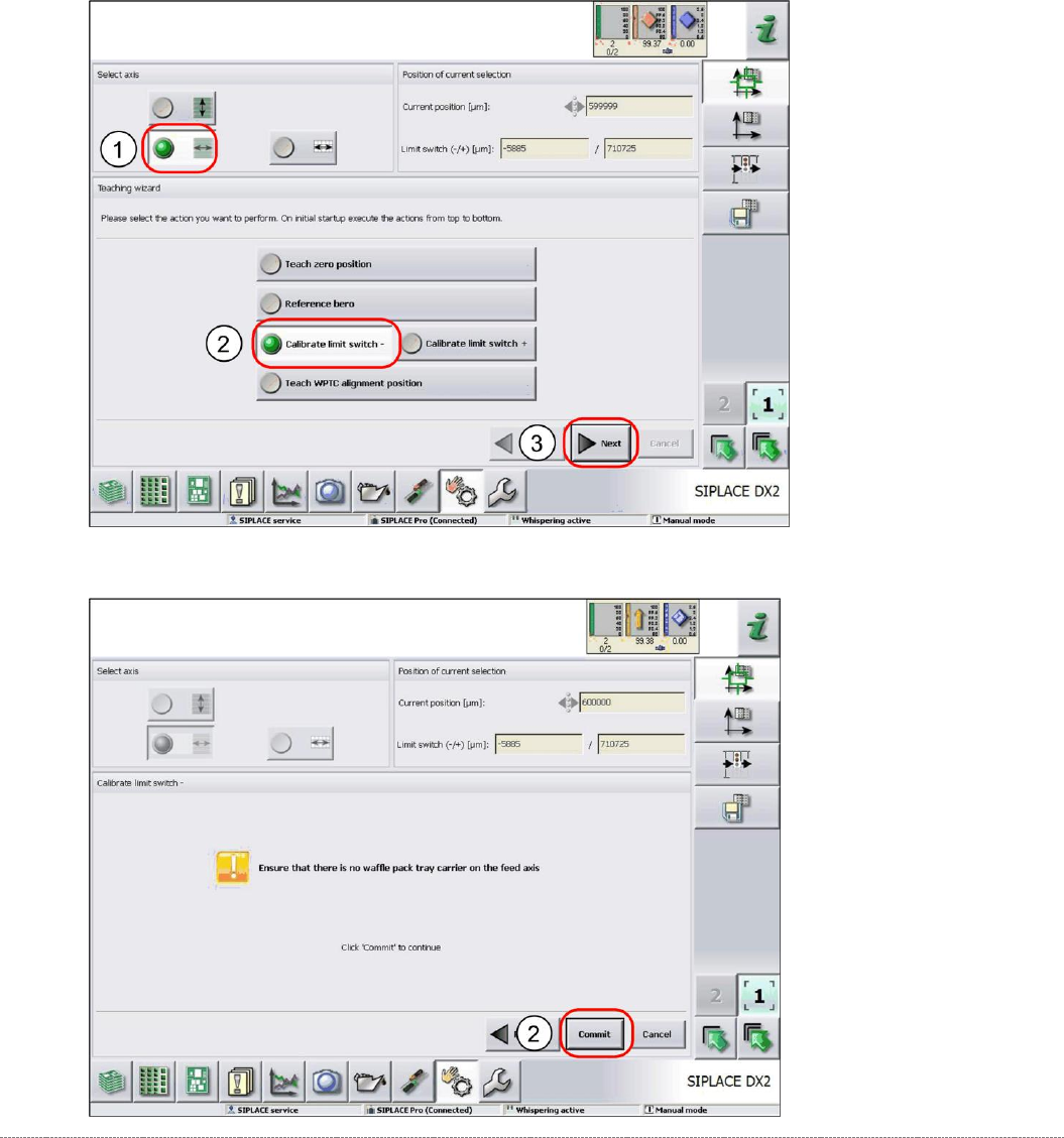
4.2.4 Calibrating the Limit Switch
The plus and minus position of the limit switches need to be calibrated.
Calibrating the limit switch -
➢ Select the feed axis (1).
➢ Select the function
Calibrate limit switch -
(2).
➢ Select
Next
(3).
➢ Follow the instruction shown and continue with
Commit
(1).
Service Manual Internal WPC5 / WPC6
Page 4-132
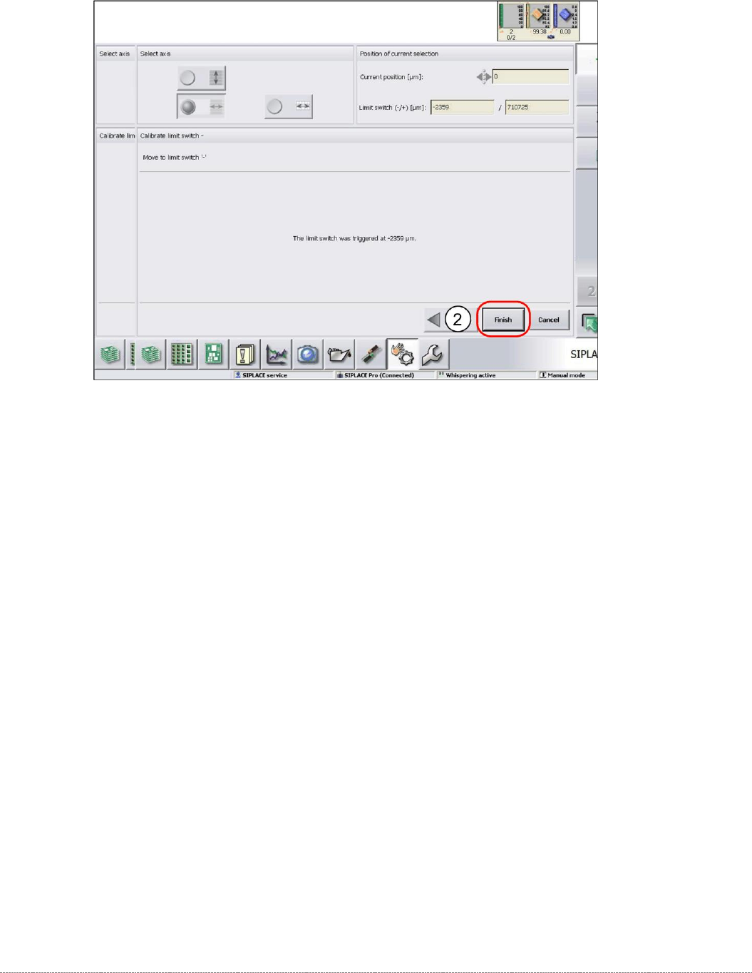
➢ Confirm the new position at which the limit switch triggers with
Finish
(1).
Calibrating the limit switch +
➢ Select the feed axis (1).
➢ Select the function
Calibrate limit switch +
and continue with the same procedure as that
used for calibrating the limit switch.
Service Manual Internal WPC5 / WPC6
Page 4-133
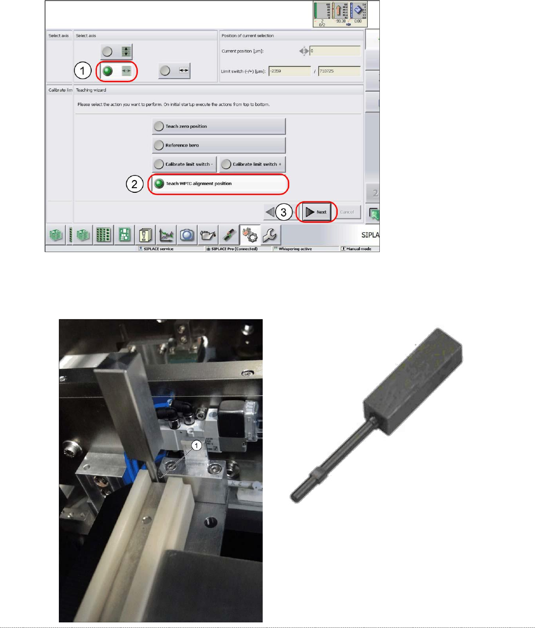
4.2.5 Teaching the WPTC Transfer Position
➢ Select the feed axis (1).
➢ Select the function
Teach WPTC alignment position
(2).
➢ Select
Next
(3).
➢ Insert the calibration pin “Adjusting gauge small WPC” [03052363-02] on the front end of the
feed axis (1).
“
Adjusting gauge small WPC
”
[03052363-02]