00197471-03_Service Manual Internal WPC5_6, EN_01-2019.pdf - 第40页
Service Manual In ternal WPC5 / WPC6 Page 3- 40 ➢ Fi t the tensioning d evice with deflection pu lley and fix into place with the two fastening screws. ➢ Readjust the belt tension (see "3.5.6 Setting the Lo ad Axi…
Service Manual Internal WPC5 / WPC6
Page 3-39
Removal / Installation
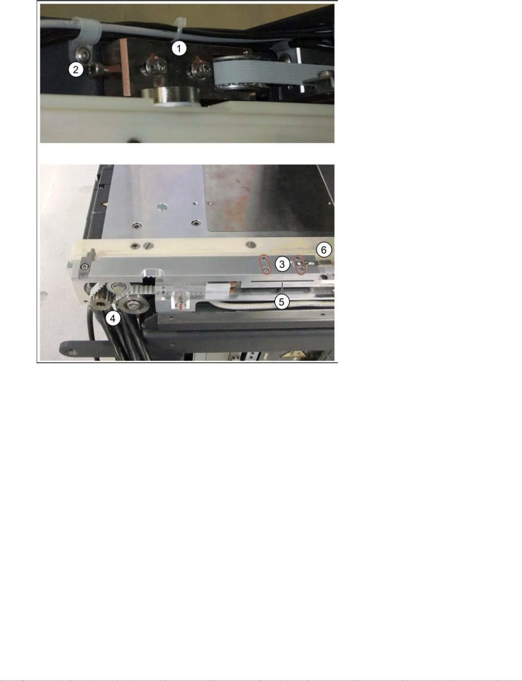
➢ Relax the belt by loosening the two fastening screws (1) sealed with locking varnish, at the
tensioning device with the deflection pulley (2).
➢ Loosen the four screws fastening the driver unit (3). The clamping unit for the toothed belt is
located underneath this.
➢ Carefully remove the driver unit. This toothed belt is now loose.
➢ Note how the toothed belt is run, so that you can fit it again correctly later on. Pull the
toothed belt over the two deflection pulleys (back and front) and out of the WPC.
➢ Remove the tensioning device and deflection pulley (2), so that you can feed in the new
toothed belt more easily. To do this, loosen the two fastening screws (1).
➢ Insert and run the toothed belt from the tensioning device (1) to the deflection pulley (4). The
toothed belt should exit below the bottom deflection pulley (4).
➢ Place the one end of the toothed belt around the deflection pulley (4) and insert into the
clamping unit (5).
➢ Place the other end around the deflection pulley of the tensioning unit (1) and then insert
into the clamping unit (5) from the other side.
Service Manual Internal WPC5 / WPC6
Page 3-40
➢ Fit the tensioning device with deflection pulley and fix into place with the two fastening
screws.
➢ Readjust the belt tension (see "3.5.6 Setting the Load Axis Belt Tension" [➙ 3-44]).
➢ Continue with chapter "4.3 Calibrating the Load Axis (WPC6 only)" [➙ 4-135].
See also...
@
3.5.1
Preparations [➙ 3-32]
@
3.5.1.3
Remove the feed axis hand guard [
➙
3-34]
3.5.4 Replace the Lifting Magnets
Spare Parts
• Lifting magnet for opening safety flap 03057345-xx
• Lifting magnet for closing the safety flap 03057344-xx
• 2 x DIN 471-4x0.4-C67 00095480-xx (retaining ring)
• Cable: lifting magnet for closing the safety flap [03058203-xx]
Preparation
➢
Remove the cover of the NSM module (see "3.5.1.1 Remove the Cover on the Load Unit"
[➙ 3-33]).
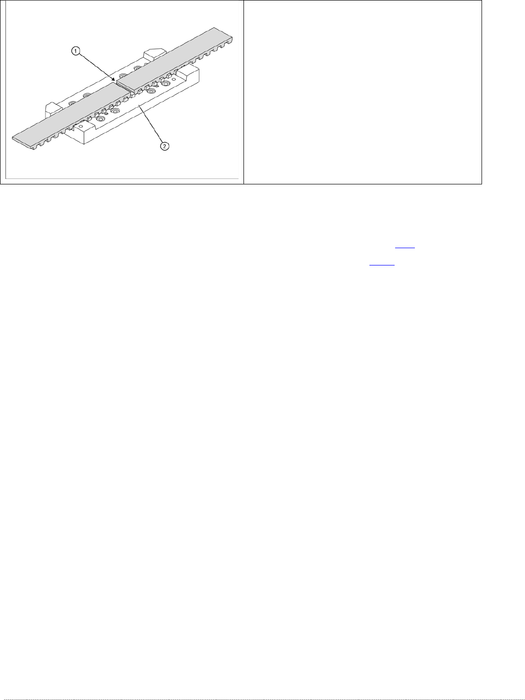
➢ The two ends of the toothed belt must be inserted
into the clamping unit (2) so that the clamping unit
teeth engage with the belt teeth. The two ends must
meet (1).
➢ Note the length of the new toothed belt. The toothed
belt is 1640 mm long/ number of teeth: 328.
➢ If the belt is too long, shorten it to the correct length.
➢ Fit the driver unit onto the clamping unit (2). Tighten
the 4 fastening screws "crosswise" with a torque of
1.3 Nm.
Service Manual Internal WPC5 / WPC6
Page 3-41
Removal / Installation
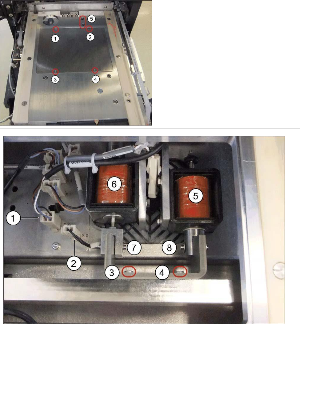
Legend
1. Connector X7 (safety sensor for hand guard)
2. Connector X2 (lifting magnet for opening the safety flap)
3. Fastening screw on magnet holder
4. Fastening screw on magnet holder
5. Lifting magnet 1 assembly / NSM [03053615-xx]
6. Lifting magnet 2 assembly / NSM [03057082-xx]
➢ Loosen the screws marked at 1 to 4 and lift off the
cover. You can now access the lifting magnets.
➢ Loosen the two screws at 5.