00197471-03_Service Manual Internal WPC5_6, EN_01-2019.pdf - 第92页
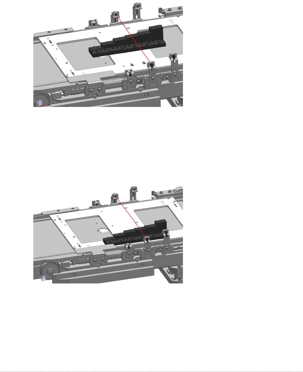
Service Manual In ternal WPC5 / WPC6 Page 3- 92 ➢ Now plug the "Adjustment- Jig crash- LS -WPC 4-6 (step) ” [0309 3895-01] to the c enter position of the base plate. ➢ Move the base plat e with the “ step gauge ” …
Service Manual Internal WPC5 / WPC6
Page 3-91
3.7.7 Adjusting the Crash Light Barriers for Component height
Tools / Equipment
Measurement setup and procedure
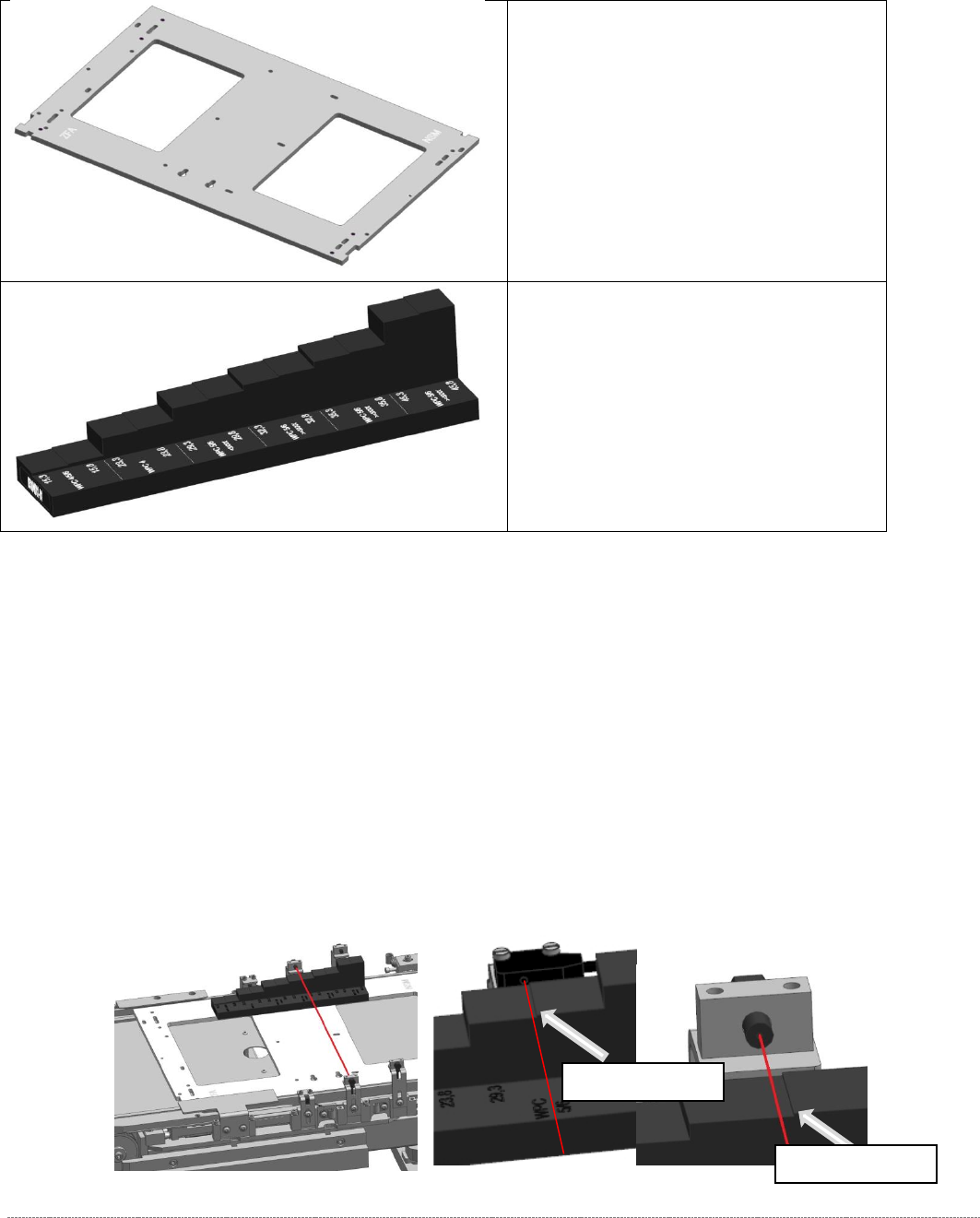
➢ Bring the „Jig for WPC4-6 base plate“ [03073064-02] with the mounted "Adjustment-Jig
crash-LS-WPC4-6 (step)” [03093895-02] in position.
The “step gauge” can be plugged at 3 positions on the base plate.
You start at the position left on the feed axis. This is directly in front of the photocell, so you
can see the position that they should reach well.
➢ Move the base plate with the “step gauge” slowly forward on the feed axis.
The Light barrier must be exactly at the level of the respective stages pair position (e.g.
29mm below).
• „Jig for WPC4-6 base plate“
[03073064-02]
• Adjustment-Jig crash-LS-WPC4-6
(step) [
03093895-02]
Switching stage
Switching stage
Service Manual Internal WPC5 / WPC6
Page 3-92
➢ Now plug the "Adjustment-Jig crash-LS-WPC4-6 (step)” [03093895-01] to the center position
of the base plate.
➢
Move the base plate with the “step gauge” slowly forward on the feed axis.
The Light barrier must be exactly at the level of the respective stages pair position.
.
➢ Now plug the "Adjustment-Jig crash-LS-WPC4-6 (step)” [03093895-01] to the right position
of the base plate.
➢
Move the base plate with the “step gauge” slowly forward on the feed axis.
The Light barrier must be exactly at the level of the respective stages pair position.

Service Manual Internal WPC5 / WPC6
Page 3-93
For the light barrier LB Type 1:
The status of the crash light barrier will be shown by the integrated LED:
• Red LED shines = not triggered (normal mode)
• Red LED does not shine = triggered (the light beam is interrupted - crash situation)
• Green LED shines = ready for operation/stability display (optimum light barrier setting)
• Green LED does not shine = ready for operation/stability display (no optimum light barrier
setting)
• LED shines red and green = correct setting (the laser beam is not interrupted)
For the light barrier LS TYP 2 :
The Status of the ligth barrier is shown on the display (7 segment) of the control unit, as well as
with the LED beside the display.
• LED on (orange) = normal function (light beam is not interrupted)
• LED off = activated (light beam is interrupted – Crash situation)
The displayed value is in normal function higher than 2500.
The threshold, at which the unit switches (LED gets off), is at about 500.
=> at 100% interruption = 0,
Step 1: setting the height
➢ Position the setting gauge with the throughout height setting on the waffle-pack tray carrier,
before the relevant transmitter/receiver:
⇨ Description signals (LED, values), see above.
➢ Move the gauge or the waffle-pack tray carrier to the trigger height setting.
➢ Check whether the crash light barrier beam is interrupted at the trigger height setting or not.
➢ Place the "Setting gauge crash WPC4 LS-6 (level)" [03093895-02] on the other two
positions. The crash beam sensor must trigger safe here.
➢ Repeat the steps described until the crash light barriers are set to the correct height and
switch reliably at all trigger points over the entire area.
Step 2: function test
➢ Check that the correct outputs are switched.
Go to the main software view and open the menu function:
⇨ Sensors and Functions ⇨ Location ⇨ Check functions for WPC ⇨ Advanced functions ⇨
⇨ WPC E/A Ports.
check that the
Crash sensor for normal components
or
Crash sensor for
high components
option is enabled
.