00197471-03_Service Manual Internal WPC5_6, EN_01-2019.pdf - 第12页
Service Manual In ternal WPC5 / WPC6 Page 3- 12 CAUTION Not open screw s with locking varnish ! RISK of C RASH ! The tower is set with these 6 screws (1) at the factory. If you open these screws , you must adjust the W…
Service Manual Internal WPC5 / WPC6
Page 3-11
3 Replacing Spare Parts
3.1 Safety Instructions
WARNING
Consider the Safety Instructions
Nonobservance of these safety instructions may cause injury to personnel and damage to the
machine!
The service work described in this manual may only be performed by specially trained service
technicians, with appropriate qualifications and expertise.
➢ Observe the safety instructions in the SIPLACE SX operating manual and those for the waffle-
pack changer (WPC), during all service work.
CAUTION
Never open screws with locking varnish
If screws sealed with locking varnish are opened, the assembly concerned will require extensive
readjustment.
➢ Only loosen screws sealed with locking varnish if the instructions in this manual explicitly ask
you to do so.
➢ If you open screws sealed with locking varnish without express instructions to do so, the WPC
must be taken to ASM for readjustment.
Preparations for service work
➢ Finish all placement operations at the SIPLACE machine.
➢ Switch the WPC off at the main switch.
➢ Carefully move the WPC out of the SIPLACE machine.
➢
Disconnect the WPC from the power supply.
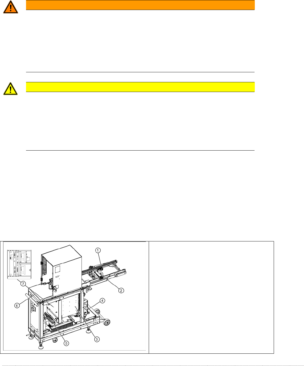
3.2 Overview of the main assemblies
Overview
1. Feed axis
2. Drive unit – feed axis
3. Lifting axis with tower
4. Drive unit – lifting axis
5. Power Supply Unit
6. Non-stop module (WPC6 only)
7. Control unit (position when fitted)
Service Manual Internal WPC5 / WPC6
Page 3-12
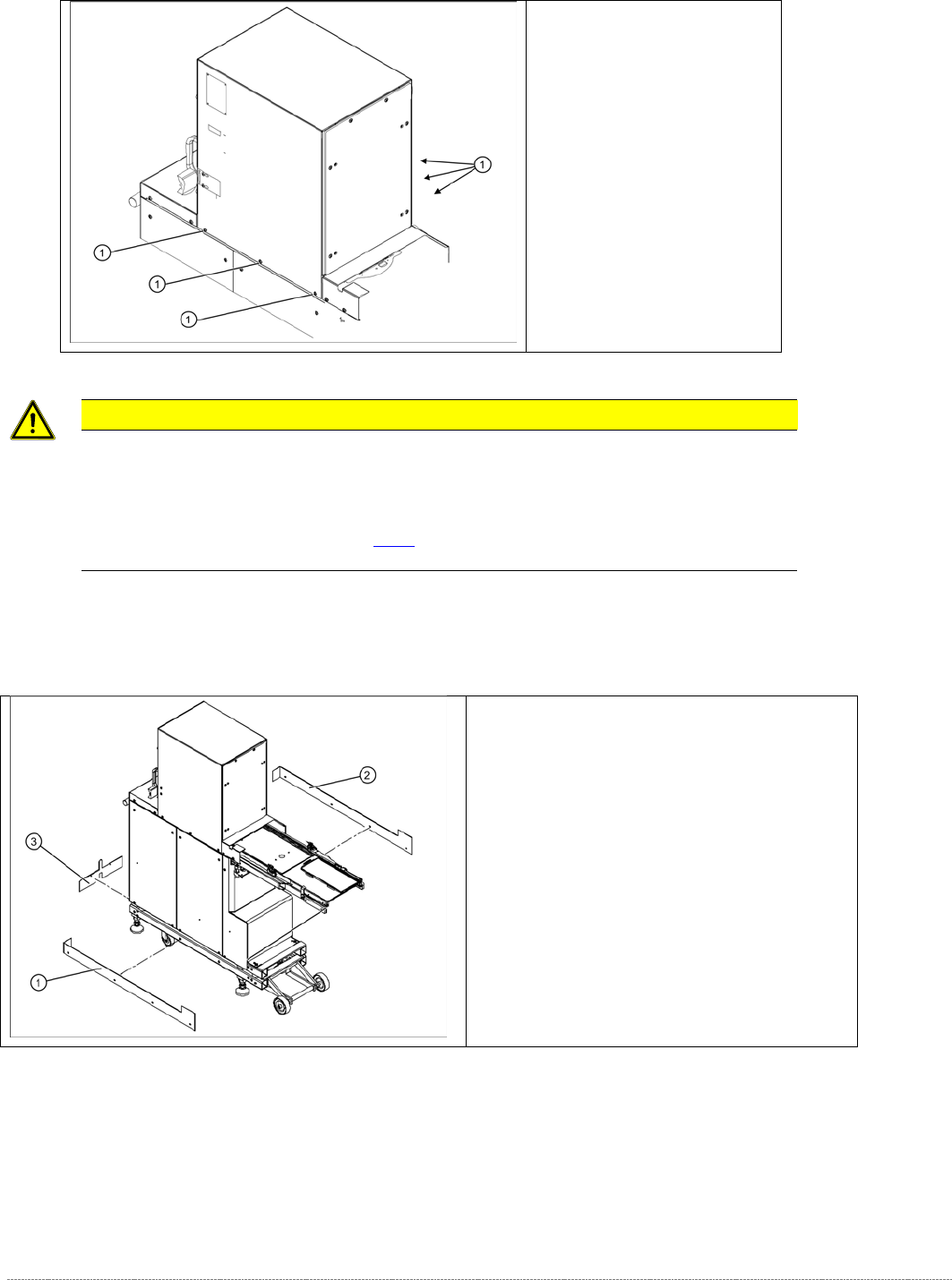
CAUTION
Not open screws with locking varnish ! RISK of CRASH !
The tower is set with these 6 screws (1) at the factory.
If you open these screws, you must adjust the WPC again, using the new „Adjustment and testing jig
WPC4-6 compl.“ [03093396-01] (see [
➙
5-145] ), or taken back to ASM for repair.
Screws sealed with locking
varnish on tower.
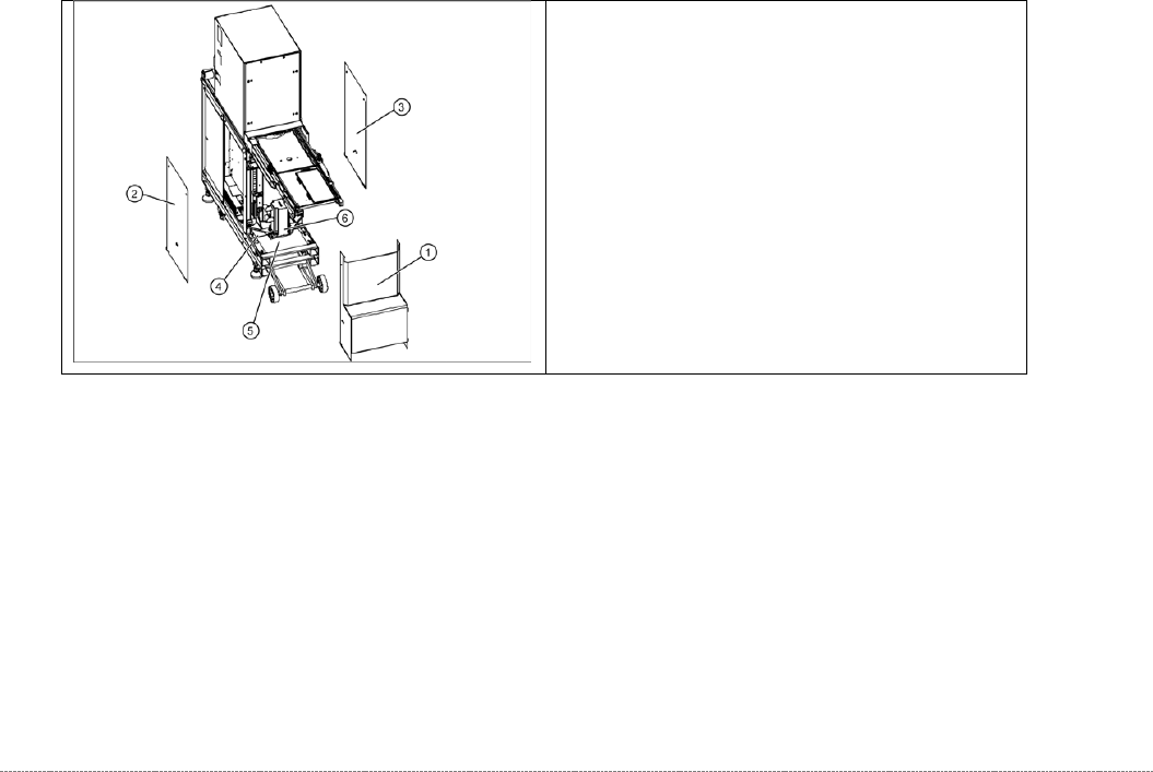
Bottom cover plates
If the WPC is configured for high machine
heights, additional cover plates will be attached to
the base.
1. right-hand cover
2. left-hand cover
3. front cover
You may need to remove these covers before
performing service work.
Service Manual Internal WPC5 / WPC6
Page 3-13
3.3 Drive Unit – Lifting Axis
3.3.1 Preparations
Tools Required
• Water pump pliers
• Belt tension device [00326015-01] with instruction guide
• Standard tool with set of Allen wrenches
Prerequisite
• Move the tower into the refill position.
• Remove all waffle pack tray carriers (WPTCs) from the tower.
• Move the tower downwards..
⇨
Check sensors and functions
⇨
Check sensors and functions of specific components
⇨
⇨
Location
⇨
Check functions for WPC
⇨
Move into transport position.
• Switch the WPC off at the main switch.
• Unplug from the power supply and secure the WPC to prevent unauthorized reactivation.
Refer to the WPC operating manual for details.
• Undock the WPC from the SIPLACE machine and move it to a suitable position for service
work.
The drive motor (6) of the lifting axis is located
behind the front cover (1). If the drive motor is
disconnected from the power supply, the drive is
fixed with a brake.
• Remove the front cover(1).
• Remove the two side covers (2) + (3).
• Loosen the 4 fastening screws in each case and
remove the two bottom hand guards (4) + (5).
The rear cover plate can be pulled out towards
the front.