00197471-03_Service Manual Internal WPC5_6, EN_01-2019.pdf - 第105页
Service Manual In ternal WPC5 / WPC6 Page 3-105 ➢ Fix the load axis drive motor (see "3.5.2 Replaci ng the Load Axis Drive M otor" [ ➙ 3- 35 ]). ➢ Fit the cover back on th e loading unit . ➢ Loosen the counte…
Service Manual Internal WPC5 / WPC6
Page 3-104
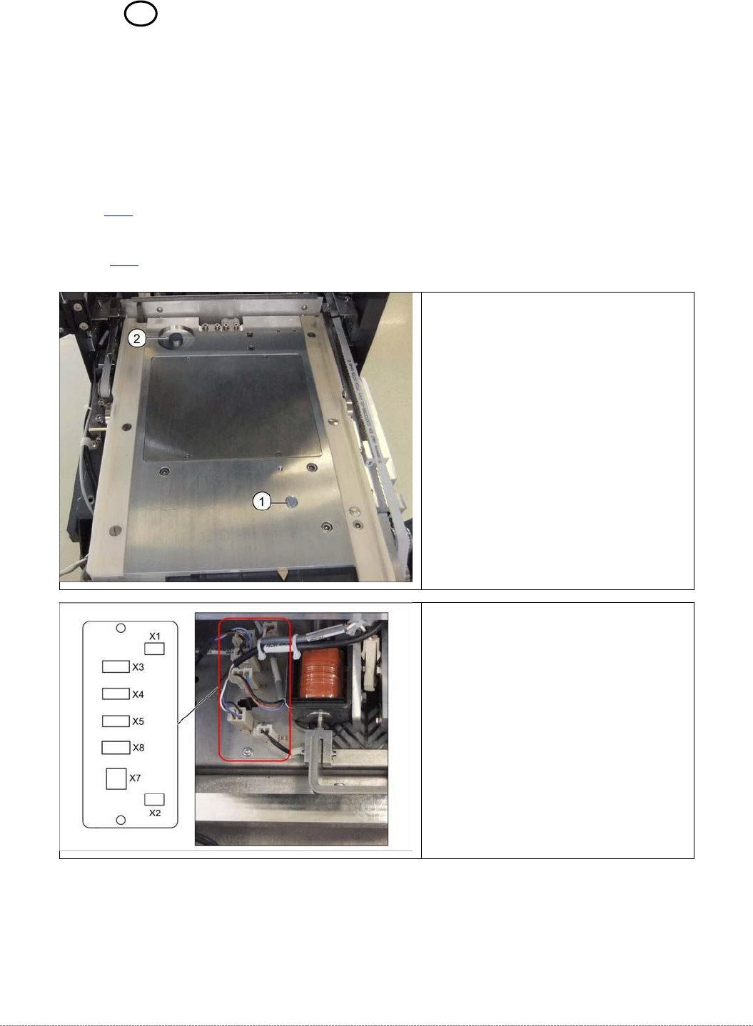
3.7.14 Sensor 18 NSM module (WPC6) - Tray correctly inserted
Spare Parts
• Sensor tray correctly inserted [03056959-xx]
Removal / Installation
➢
Remove the cover on the load unit (see "3.5.1.1 Removing the Cover on the Load Unit"
[➙ 3-33]).
➢
Remove the load axis drive motor (see "3.5.2 Replacing the Load Axis Drive Motor"
[➙ 3-35]), to gain access to the sensor from below.
Legend
7. Sensor tray correctly inserted.
8. Sensor tray detection load axis.
➢ Disconnect connector X4 from the
circuit board.
Service Manual Internal WPC5 / WPC6
Page 3-105
➢ Fix the load axis drive motor (see "3.5.2 Replacing the Load Axis Drive Motor" [➙ 3-35]).
➢ Fit the cover back on the loading unit.
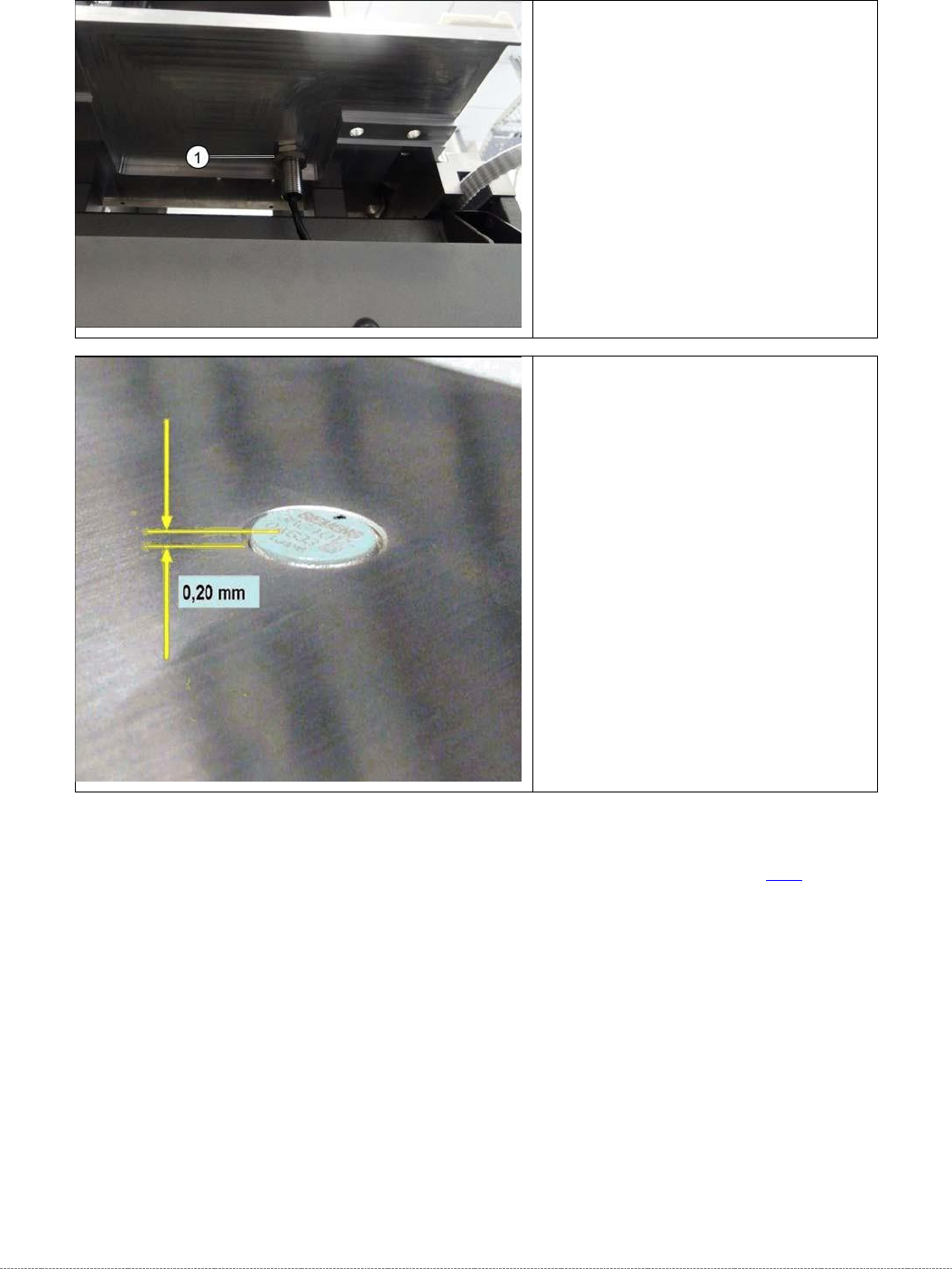
➢ Loosen the counternut fastening
the sensor on the underside of the
base plate and unscrew the sensor
(1).
➢ Screw the new sensor into place.
➢ The sensor should protrude at least
0.2 mm above the table plate.
➢ Use a counternut to fix the sensor
on the underside
(1).
➢ Reconnect connector X4 to the
circuit board.
Service Manual Internal WPC5 / WPC6
Page 3-106
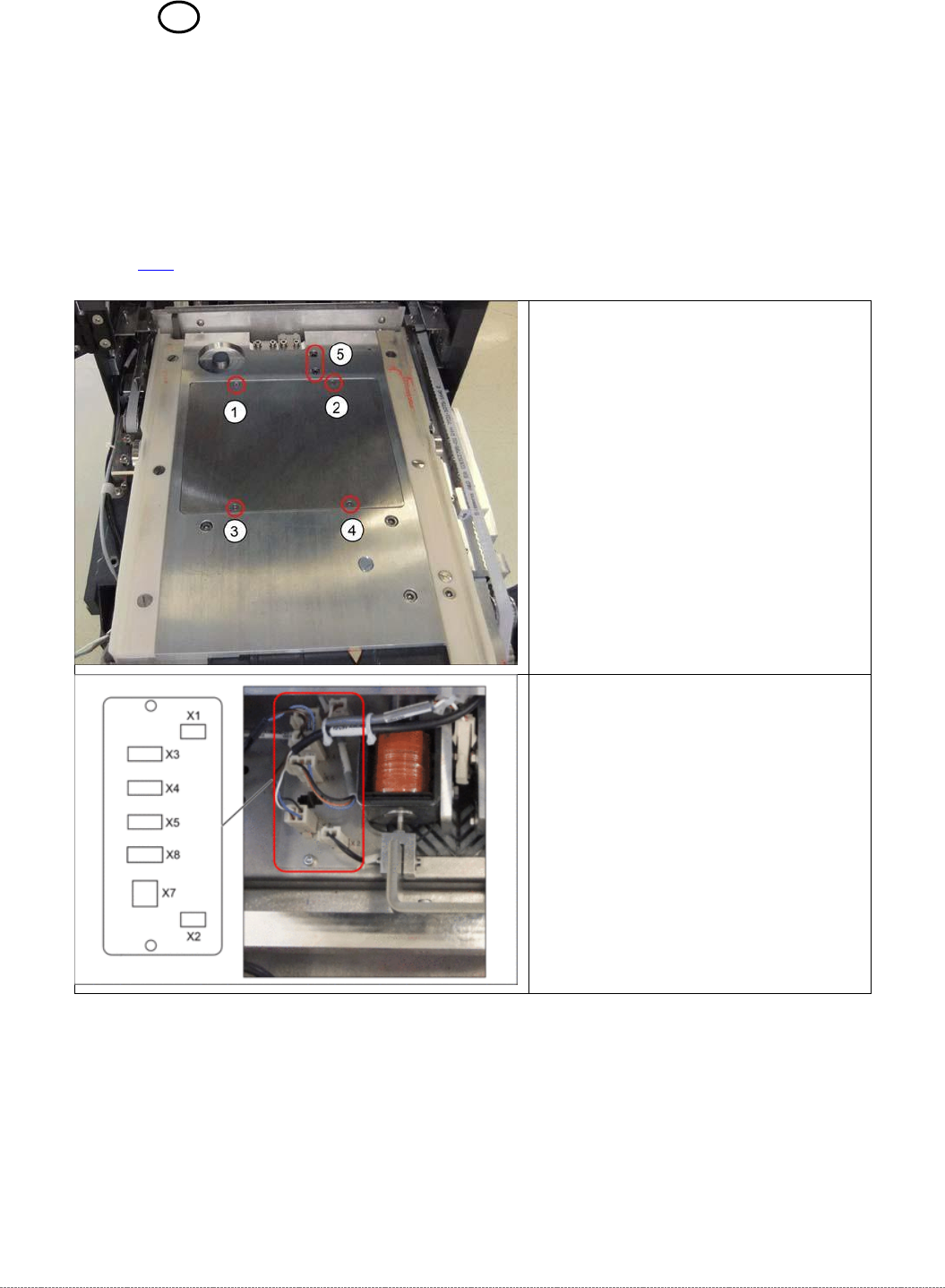
3.7.15 Sensor 15 NSM-Modul (WPC6) – Safety flap open
Spare Part
• Sensor safety flap open [03056958-xx]
Removal / Installation
➢ Remove the cover on the load unit (see "3.5.1.1 Remove the Cover on the Load Unit"
[➙ 3-33]).
➢
Loosen the screws marked at 1 to 4
and lift off the cover.
➢ Disconnect connector X3 for the
safety flap when open from the
circuit board.