00197471-03_Service Manual Internal WPC5_6, EN_01-2019.pdf - 第52页
Service Manual In ternal WPC5 / WPC6 Page 3- 52 3.6.3.5 Repla ce the S ervo Am plifier f or the L ifting A xis and Feed A xis Spare Parts • Servo amplifier T BS 200/3Z1 [03048005 -xx] fo r f eed axis • Servo amplifier …

Service Manual Internal WPC5 / WPC6
Page 3-51
3.6.3.4 Replace the Axis card
Spare Part
• Axis KSP A364 analog [03041865-xx]
Removal / Installation
➢ Wear the ESD wristband.
➢ Loosen the 2 screws fastening the front plate of the axis card.
➢ Carefully pull the axis card (see "3.6.3 Control Unit" [➙ 3-48]) out of the control unit.
➢ Carefully insert the new axis card.
➢ Make sure that the axis card engages properly.
➢
Tighten the 2 screws fastening the front plate of the axis card.
Settings
➢ Perform a firmware download for the axis card..
⇨ Configure, update and calibrate the machine) ⇨ Embedded Software ⇨ Update subsystem ⇨
⇨ Automatic tray feeder axis.
➢ For more information, refer to the Online Help for the station software.

Service Manual Internal WPC5 / WPC6
Page 3-52
3.6.3.5 Replace the Servo Amplifier for the Lifting Axis and Feed Axis
Spare Parts
• Servo amplifier TBS 200/3Z1 [03048005-xx] for feed axis
• Servo amplifier TBS 200/10X1 [00344204-xx] für lifting axis
Removal / Installation
➢ Wear the ESD wristband.
➢ Loosen the 4 screws fastening the plexiglass cover and remove this.
➢ Press down the lock under the board of the relevant servo amplifier (see "3.6.3 Control Unit"
[➙ 3-48]).
➢ Carefully pull the servo amplifier out of the control unit.
➢ Make sure that the servo amplifier matches the relevant axis. Compare the part numbers of
the "old" servo amplifier with those of the new one.
➢ Carefully insert the new servo amplifier.
➢ Make sure that the servo amplifier engages properly.
➢ Refit the plexiglass cover and screw into place.
Settings
• No settings are required.
Service Manual Internal WPC5 / WPC6
Page 3-53
3.6.3.6 Replace the Servo Amplifier for the Non-Stop Module
Spare Part
• Servo amplifier TBS 200/3Z1 [03048005-xx] for Non-Stop-Module
Removal / Installation
➢ Move the tower into the refill position and switch the WPC off.
➢ Wear the ESD wristband.
➢ Remove the second side cover from the control unit side.
➢ Loosen the 4 screws fastening the plexiglass cover and remove this.
Settings
• No settings are required.
See also...
@
3.6.3
Control Unit [➙ 3-48]
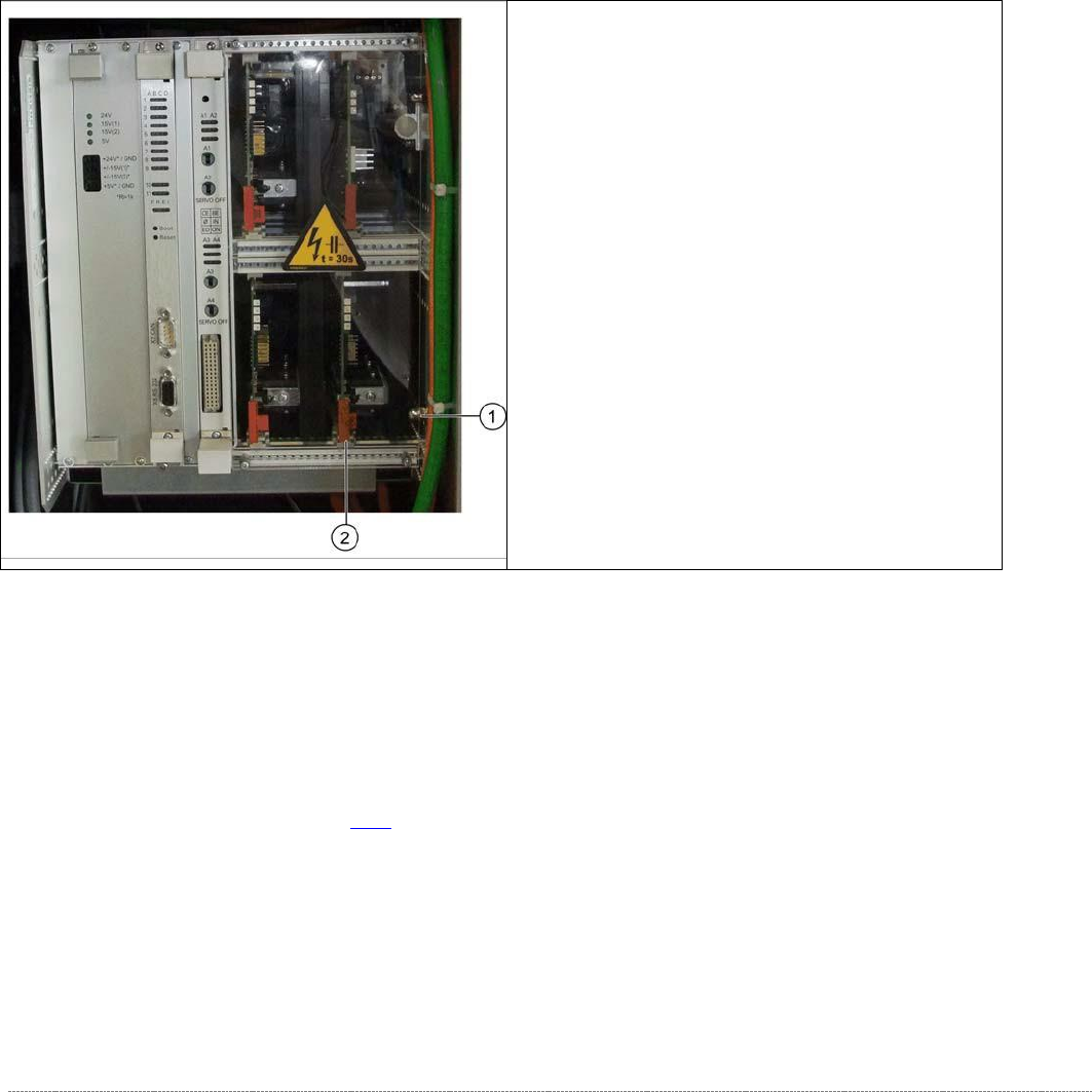
➢ Loosen and remove the lower cap nut on the
slot unit (1).
➢ Loosen the counternut and pull the screw out
towards the back until you can remove the
servo amplifier.
➢ Press the lock under the board of the servo
amplifier (2).
➢ Carefully pull the servo amplifier out of the
control unit.
➢ Carefully insert the new servo amplifier.
➢ Make sure that the servo amplifier engages
properly.
➢ Tighten the cap nut and counternut.
➢ Refit the plexiglass cover and screw into place.