00197471-03_Service Manual Internal WPC5_6, EN_01-2019.pdf - 第65页
Service Manual In ternal WPC5 / WPC6 Page 3- 65 3.6.5.2 Repla cing the Em erge ncy STOP and Prote ctive Doo r Monito r (W PC6 onl y) Spare Part • Emergenc y S TOP and g uard door moni tor [03056745- xx] Removal / Insta…
Service Manual Internal WPC5 / WPC6
Page 3-64
3.6.5 Power Supply Unit
3.6.5.1 Replacing the Protective Contactor Combination (SSK)
Spare Part
• Protective contactor combination (SSK) 3TK2828-
1BB41 [00372649-xx]
Removal / Installation
➢ Label all connections for easier installation later.
➢ Unplug all connections from the protective contactor combination.
➢ Lever the protective contactor combination off the mounting rail.
➢ Connect the new protective contactor combination to the mounting rail and restore the
electrical connections..
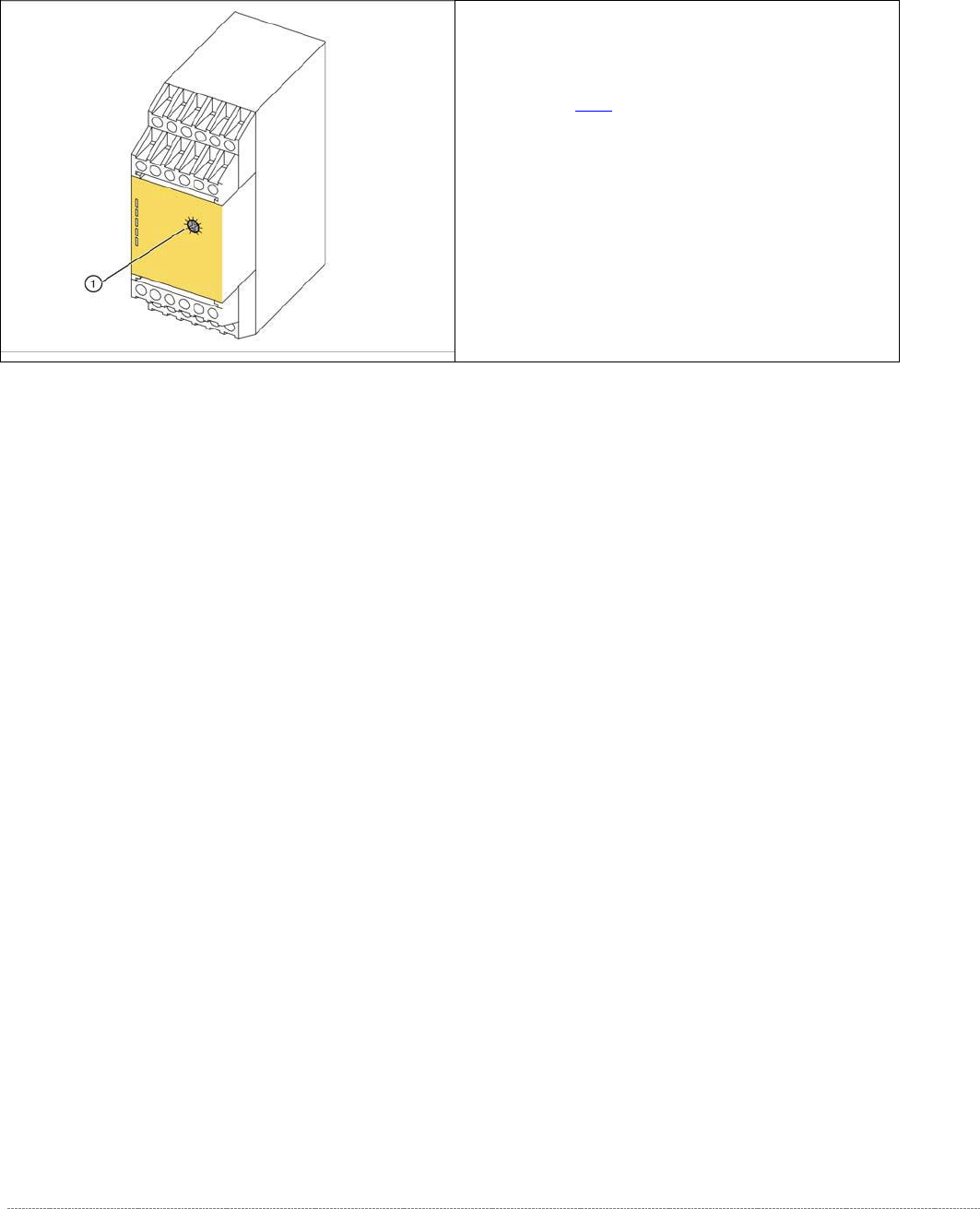
Settings
➢ Adjust the setting screw (1) to a value of 0.5 (seconds). If the value is set too high, an error
message will be issued.
➢ Seal the setting screw with locking varnish.
The protective contactor combination (SSK) is
located at the front of the electrical unit (see "3.6.2
Overview"[➙ 3-47]).
1. setting screw
Service Manual Internal WPC5 / WPC6
Page 3-65
3.6.5.2 Replacing the Emergency STOP and Protective Door Monitor (WPC6 only)
Spare Part
• Emergency STOP and guard door monitor [03056745-xx]
Removal / Installation
➢
➢
➢
➢
➢
➢
➢
➢
➢
➢
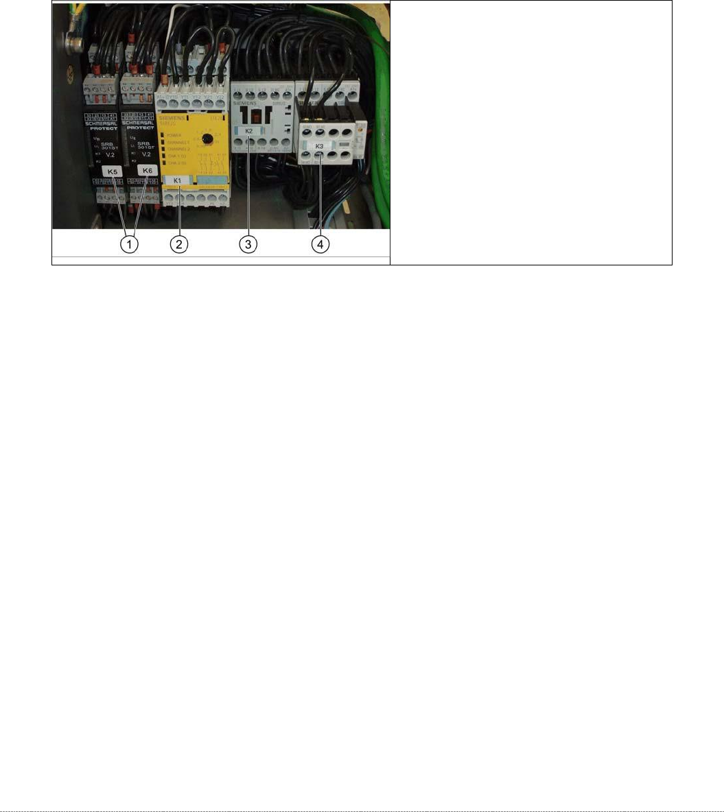
➢ Label all connections for easier installation later.
➢ Unplug all connections from K5/K6.
➢ Lever the K5/K6 off the mounting rail.
➢ Connect the new K5/K6 to the mounting rail and restore the electrical connections.
1. Protective door monitor and
emergency STOP, K5 and K6
2. SSK K1
3. Contactor K 2
4. Contactor K 3

Service Manual Internal WPC5 / WPC6
Page 3-66
3.6.5.3 Replacing the Inrush Current Limitation Board
The inrush current limitation boards are located at the back of the electrical unit (see "3.6.4.2
Power Supply for WPC5" [➙ 3-61] for WPC5 and "3.6.4.3 Power Supply for WPC6" [➙ 3-62] for
WPC6).
Spare Part
• Inrush current limitation board WPC [03047752-xx] (A1)
• Inrush current limitation board WPC NS [03056232-xx] (A2) (WPC6 only)
Removal / Installation
➢ Label all connections for easier installation later.
➢ Unplug all connections from the inrush current limitation board.
➢ Lever the inrush current limitation board off the mounting rail.
➢ Connect the new inrush current limitation board to the mounting rail and restore the
electrical connections.
Settings
• No settings are required.
See also...
@
3.6.5
Power Supply electric [➙ 3-64]