00197471-03_Service Manual Internal WPC5_6, EN_01-2019.pdf - 第161页
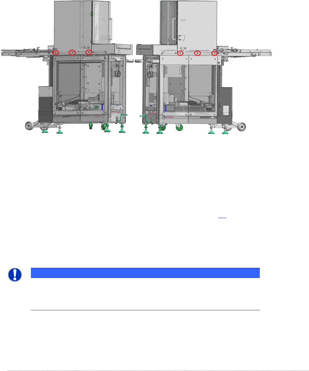
Service Manual In ternal WPC5 / WPC6 Page 5-161 5.5.5 Settings for the stopper strip (rear, top guide rail) Figure 5. 20 : Scre ws securing the tower cover to the WPC frame NOTICE Using 2 base plates In particular when…
Service Manual Internal WPC5 / WPC6
Page 5-160
If the position needs to be corrected, the tower cover must be moved.
To do this, you should release (but not remove) all six screws that secure the tower cover to the
frame of the WPC.
Figure 5.19: Screws securing the tower cover to the WPC frame
Now move the top cover (tower cover) to achieve a gap of 0.2 mm between the two front guide rails
and the gauge.
Now remove the gauge from Division 5 and insert it in division 24 (fifth from the top).
Clamp the gauge in the same way as you did in Division 5 , with the „Gauge base setting base plate
position“ [03110862-xx] touching the guide rails of the lifting axis. See section 5.3.
Move the tower up.
Use a feeler gauge to check the gap between the front guide rails and the baseplate of the gauge.
It should be in the range 0.2 mm to 0.7 mm.
NOTICE
Using 2 base plates
If you are using two gauges, you can now set the bottom and top positions at the top,
front guide rail together.
Finally tighten the 6 securing screws for the cover again. To do this, use a torque wrench set to a
tightening torque of 5 Nm.
Then apply red screw locking varnish [00318197-01] to these screws.
Service Manual Internal WPC5 / WPC6
Page 5-161
5.5.5 Settings for the stopper strip (rear, top guide rail)
Figure 5.20: Screws securing the tower cover to the WPC frame
NOTICE
Using 2 base plates
In particular when you are setting the stopper strip, it is recommended that you use 2
gauges in the tower as described above.
If you are only using one gauge, insert it in Division 24 (fifth from the top).
Clamp the gauge in the same way as described above, with the „Gauge base setting base plate
position“ [03110862-] touching the guide rails of the lifting axis.
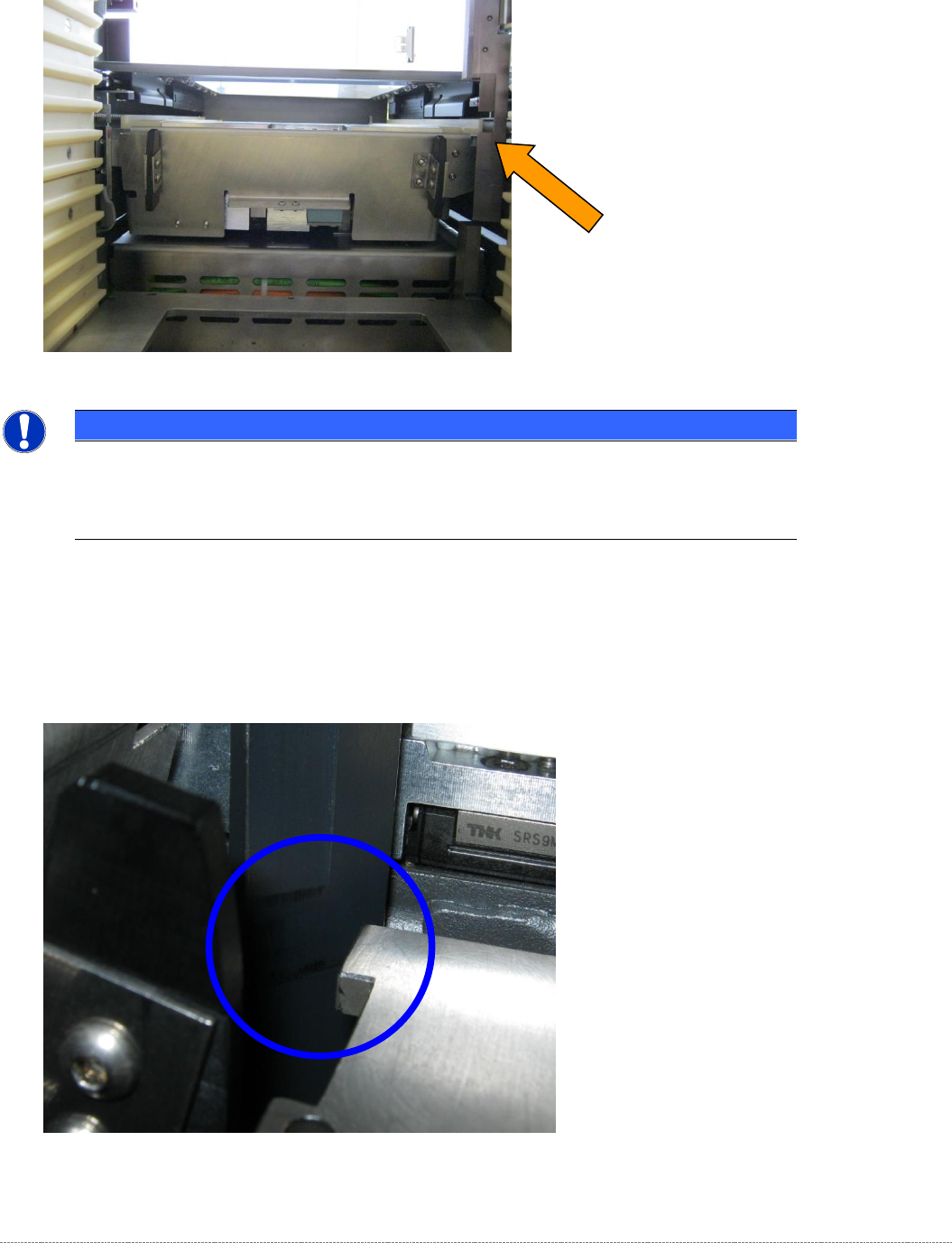
Then position the tower in such a way that the gauge is located between the two alignment marks on
the small, flat surface of the rail.
Figure 5.21: Alignment marks on the stopper strip (top, rear guide rail, bottom position)
Service Manual Internal WPC5 / WPC6
Page 5-162
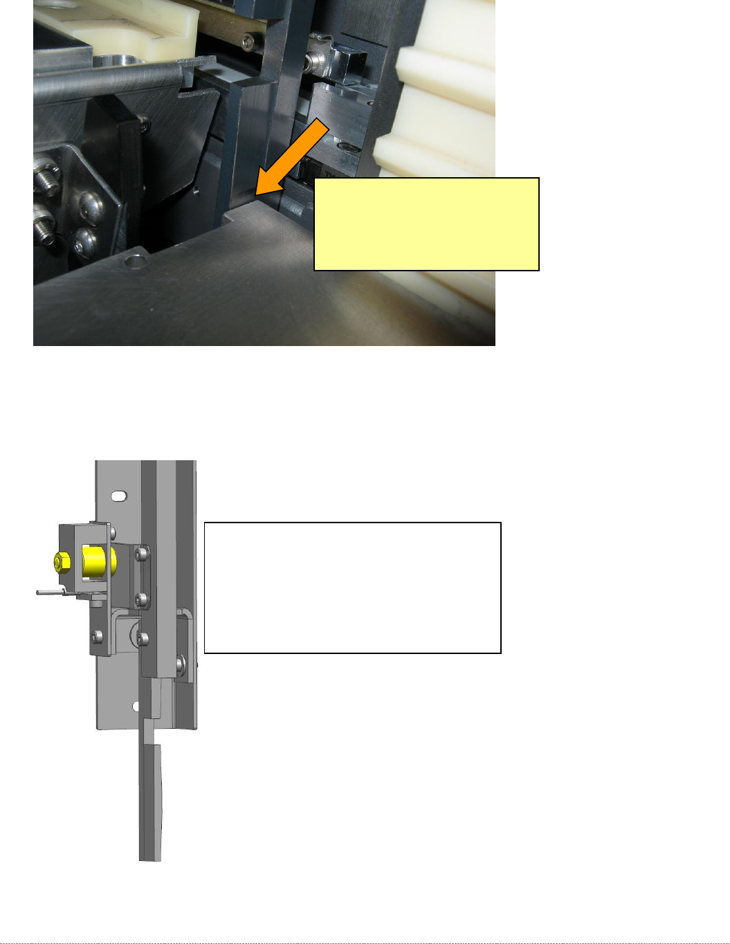
Now use a feeler gauge to set a gap of 0.2 mm between the guide rail and the baseplate of the
gauge.
Figure 5.22: Setting the bottom position of the rear, top stopper strip (guide rail) to 0.2 mm
If you identify that the gauge and the rail are not parallel (see the figure above), you can change the
angle of the rail using the magnet.
Figure 5.23: Setting the stopper strip at right angles to the mounting bracket using the magnet.
If you wish to remove the stopper strip in order to set the angle, proceed as follows.
Set a gap of 0.2 mm here.
Take particular care to ensure that the
gauge is parallel with the surface of the
rail. If these are not parallel, the rail is not
perpendicular to the mounting surface of
the stopper strip unit.
The magnet also acts as the stopper for the
stopper strip.
If you release the locknut at the rear, you
can twist the magnet to set the inclination of
the stopper strip.