00197471-03_Service Manual Internal WPC5_6, EN_01-2019.pdf - 第169页
Service Manual In ternal WPC5 / WPC6 Page 5-169 The deflector shou ld always be fitted as parallel as possible to the saf ety flap. Pay attention that the b lack plastic part alwa y s covers t he met al edge, on which …
Service Manual Internal WPC5 / WPC6
Page 5-168
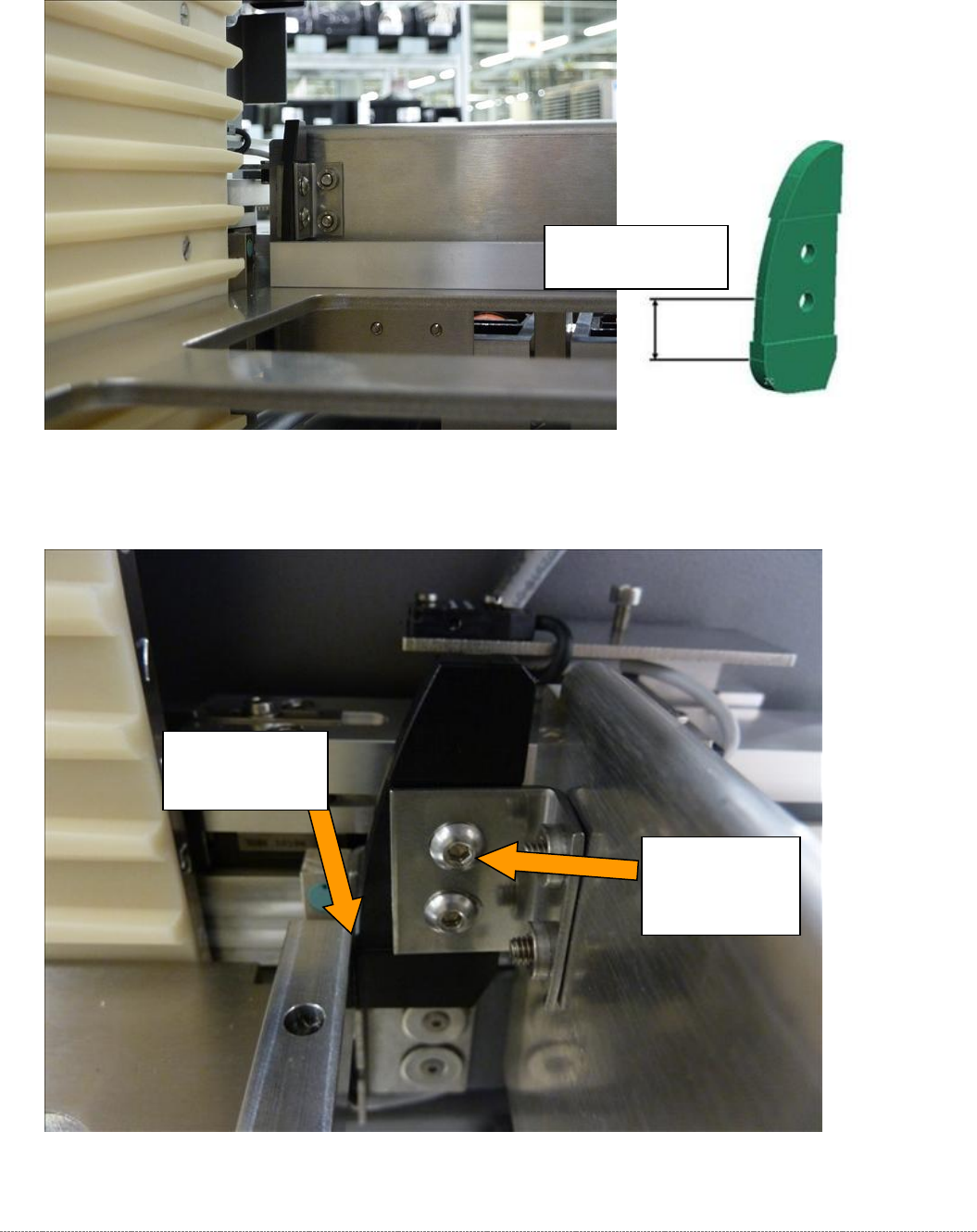
Now move the tower to the position at which the gauge with the attached "Strip for stopper flap,
complete" [03093815-xx]", is precisely in the setting range of the deflectors.
Move the gauge with the strip into the setting range of the deflectors.
Figure 5.33: Setting the deflectors on the safety flap.
Now set the gap to the deflector in such a way that the strip just touches the deflector.
Figure 5.34: Setting the deflectors on the safety flap.
Deflector lightly
touching the
bar.
Screws for
adjusting and
securing the
deflectors.
Setting range on
the deflector
Service Manual Internal WPC5 / WPC6
Page 5-169
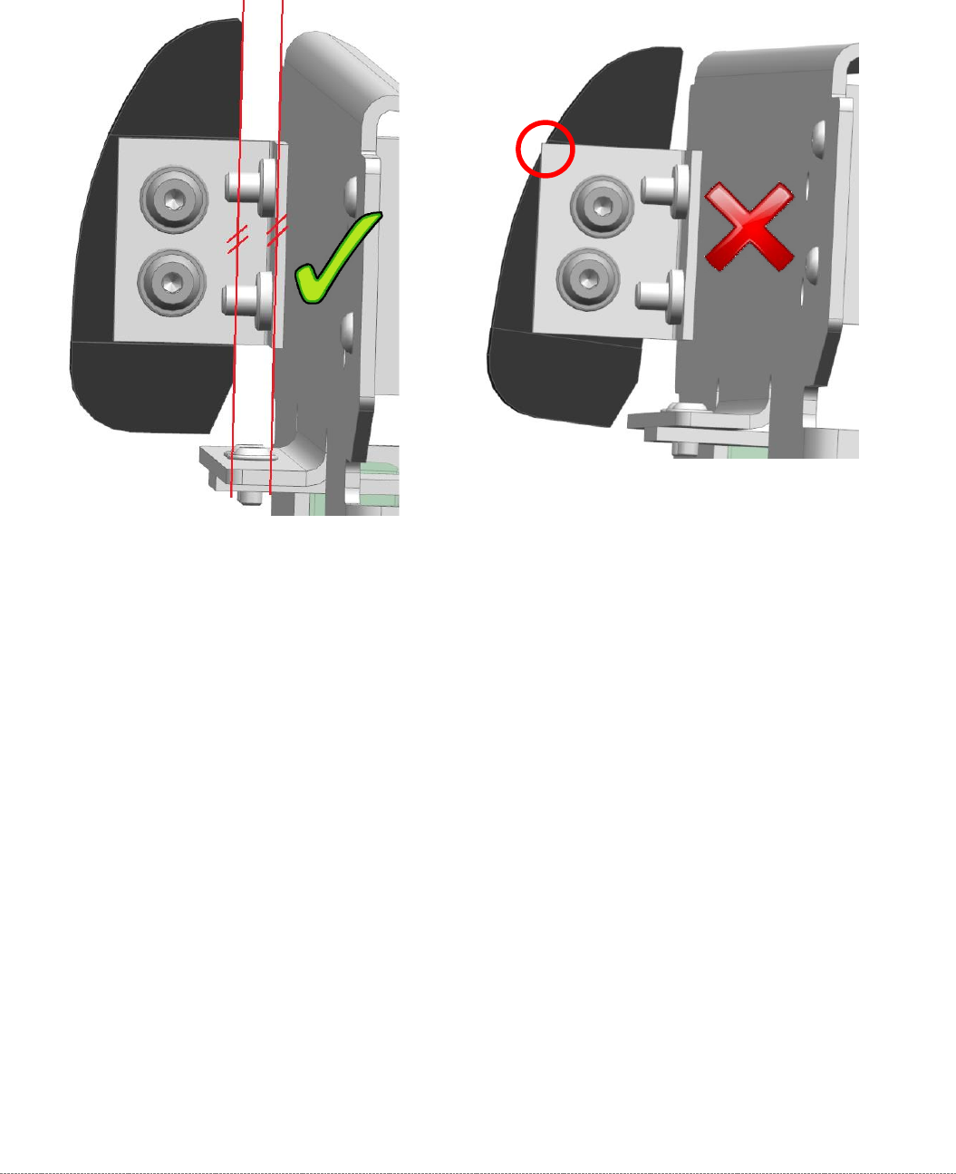
The deflector should always be fitted as parallel as possible to the safety flap.
Pay attention that the black plastic part always covers the metal edge, on which it is mounted, so
that no interfering edge occurs.
Service Manual Internal WPC5 / WPC6
Page 5-170
5.8 Checking the clearance at the edge of the waffle pack tray carrier
Remove the gauge(s) from the tower and push a waffle pack tray carrier into the tower.
Move the tower to a position where the metal plate (waffle pack tray carrier) is at the same height as
the transfer point to the loading axis.
Push a magnet intended to secure a tray in the waffle pack tray carrier into the left front corner of the
carrier.
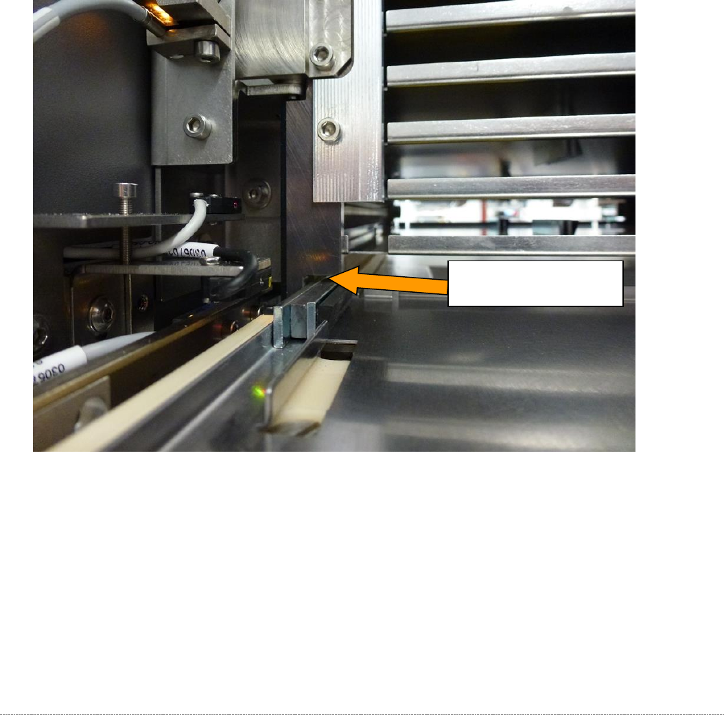
Manually move the metal plate (waffle pack tray carrier) through the recess at the stopper strip and
check the clearance.
Figure 5.35: Checking the clearance for magnets at the recess on the stopper strip.
The required clearance
is approximately 1.3 mm.