00197471-03_Service Manual Internal WPC5_6, EN_01-2019.pdf - 第59页
Service Manual In ternal WPC5 / WPC6 Page 3- 59 ➢ Lever the mounting fram e (2) out of the contr ol unit holes with a su itable tool (e.g. screwdriver). ➢ Remove the mount ing frame with fan. ➢ Mark the installation po…
Service Manual Internal WPC5 / WPC6
Page 3-58
3.6.3.9 Replace the Fan
Spare Parts
• Axial fan [00319141-xx]
Overview
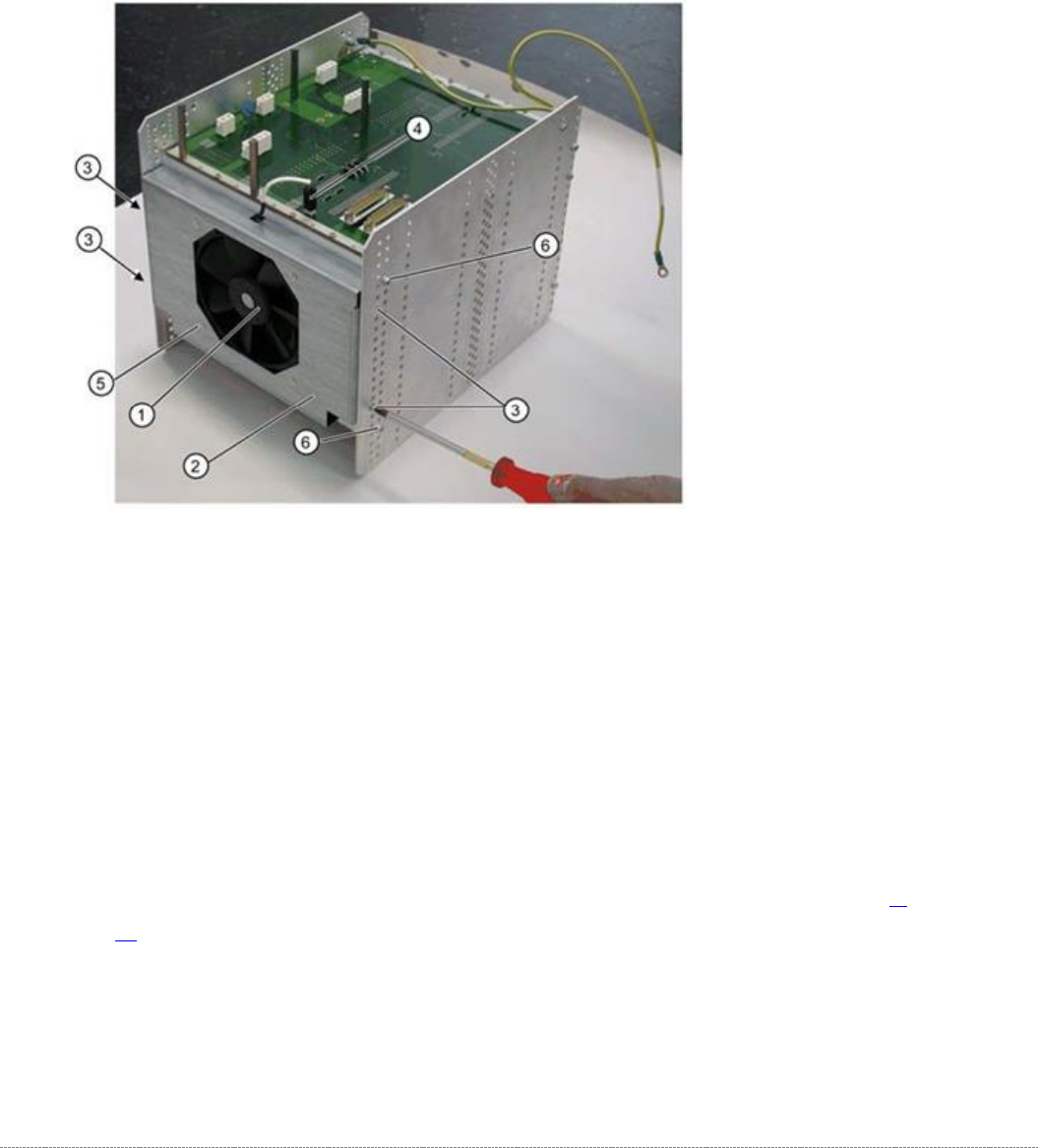
The fan (1) is located on the underside of the control unit and is fitted with the help of a mounting
frame (2).
1.
Fan
2. Mounting frame
3. 4 x mounting frame fastening screws
4. Electrical connection for fan
5. 4 x fastening screws for fan on mounting frame
Removal
➢ Dismantle the complete control unit (see "3.6.3.8 Replace the Complete Control Unit" [➙ 3-
55]).
➢ Unplug the connection cable (4) and the back plane X17.
➢ Mark the installation position of the mounting frame (2) on the relevant control unit holes.
➢ Loosen the 4 fastening screws (3) on the mounting frame (2).
➢
The mounting frame (2) can be levered more easily out of the holes, if you also loosen the 2
screws (6) on the control unit.

Service Manual Internal WPC5 / WPC6
Page 3-59
➢ Lever the mounting frame (2) out of the control unit holes with a suitable tool (e.g.
screwdriver).
➢ Remove the mounting frame with fan.
➢ Mark the installation position of the fan (1) in the mounting frame. Make a note of the
direction in which air is blown out! The fan takes in air from below and blows it into the inside
of the control unit.
➢ Loosen the 4 screws (5) fastening the fan (1) to the mounting frame.
➢ Remove the fan.
Installation
➢ Fit the fan in the mounting frame. Note the position of the connection cable.
➢ Carefully lever the mounting frame with its openings into the holes.
➢ Fit the mounting frame with the fan in the control unit.
➢ Tighten the two screws (6) on the control unit and reconnect to the power supply.
➢ Fit the complete control unit (see "3.6.3.8 Replace the Complete Control Unit" [➙ 3-55]).
Settings
➢ Check the flow of air from the fan. The fan takes in air from below and blows it into the
inside of the control unit.
Service Manual Internal WPC5 / WPC6
Page 3-60
3.6.4 Overview of Electrical Components
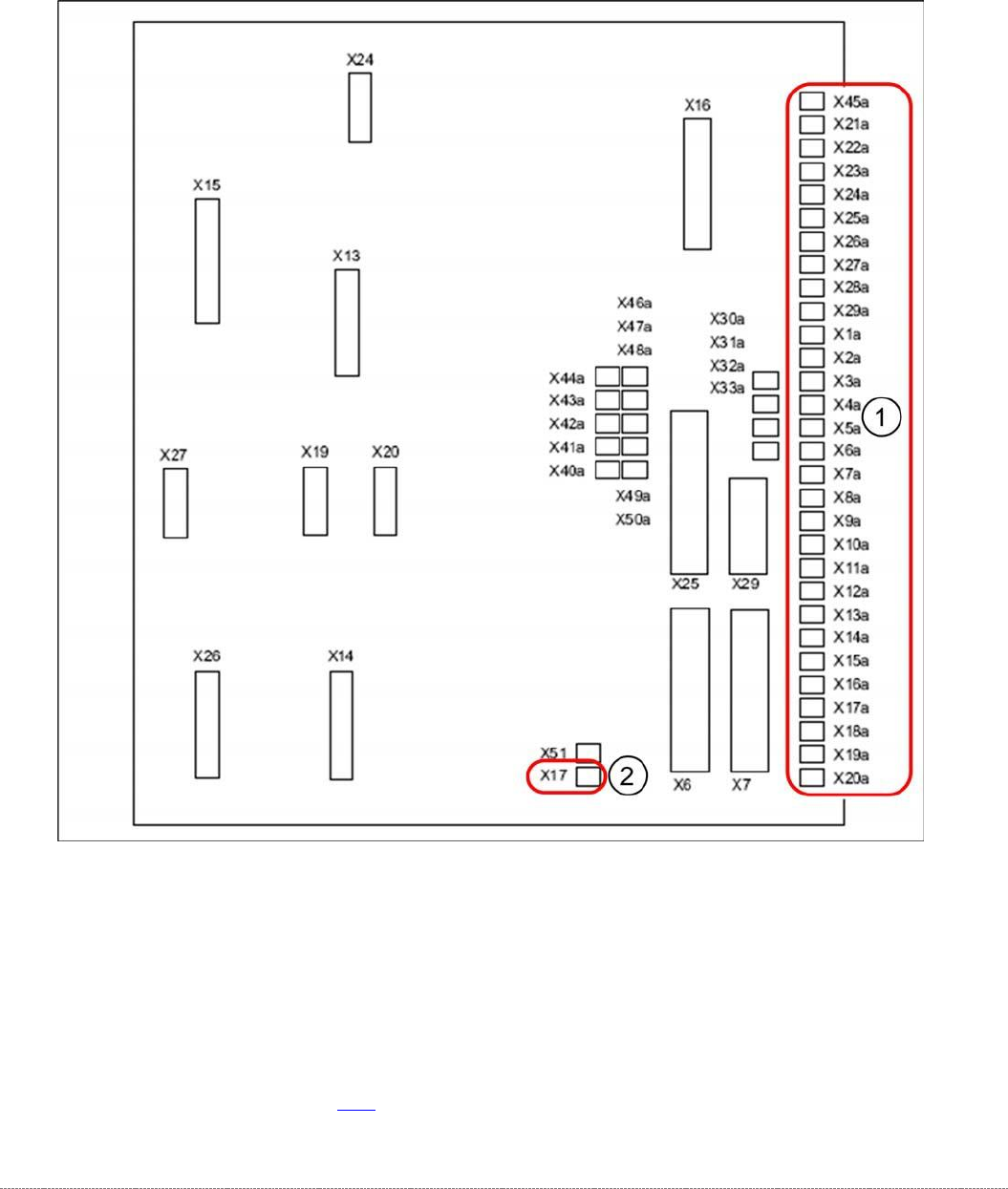
3.6.4.1 Back Plane
Back view – Overview
Legend
1. Connections for limit switches, sensors and light barriers
2. Fan connection
For a detailed overview of the connections, see "3.7.1.3 Detailed Connections for Limit Switches,
Sensors and Light Barriers" [➙ 3-72].