00197471-03_Service Manual Internal WPC5_6, EN_01-2019.pdf - 第99页
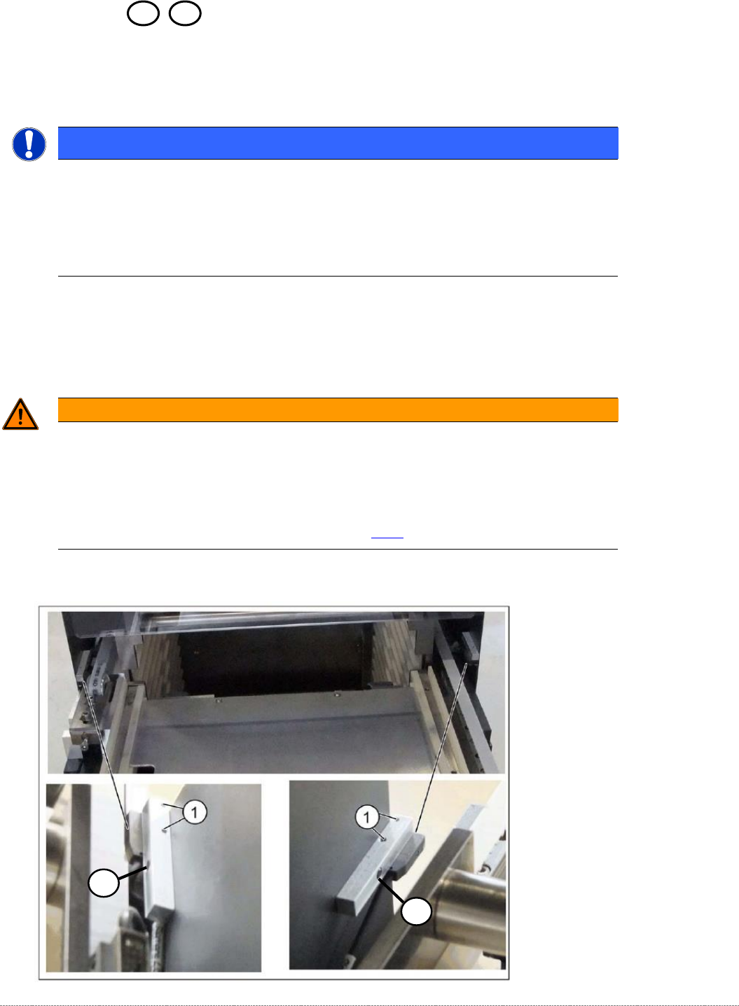
Service Manual In ternal WPC5 / WPC6 Page 3- 99 3.7.11 13 Safety S witc h Spare Part • Safety switch, closed (safet y switch with cable) [03062919- xx] Removal / Installatio n ➢ Mark the installation pos ition of the s…

Service Manual Internal WPC5 / WPC6
Page 3-98
Settings
➢ Check the function and correct position of the limit switch. The limit switch must switch when
the lifting axis moves over the switch (3) (end position).
➢ To do this, open the following function in the main view:
⇨ Sensors and Functions ⇨ Location ⇨ Check functions for WPC ⇨ Advanced functions
.
➢ Select the
Feed axis
button in the Axis input area.
➢ Select the
Limit switch
+ button in the input area (see also "4.1.4 Calibrating the Limit Switch"
[➙ 4-122]).
⇨
The lifting axis will be moved so that an actuator on the lifting axis moves over the limit
switch.
The limit (end position) will be calculated.
⇨
Go to the main view and open the menu function
⇨ Sensors and Functions ⇨ Location ⇨ Check functions for WPC ⇨ Advanced functions ⇨ WPC E/A
Ports
.
Make sure that the
Lifting axis bottom limit switch
view option is enabled.
⇨
A dialog box will open and the calculated value will be shown. The permissible limits
(minimum/maximum position) will also be shown. The end position must be within these
limits.
➢ Check the permissible limits against the value actually measured.
➢ If necessary, correct the mechanical position of the limit switch and repeat the
measurement procedure.
➢ If the value is within the permissible limits, save the data by clicking on
Accept
.
➢
Seal the two mounting bracket fastening screws with locking varnish.
Service Manual Internal WPC5 / WPC6
Page 3-99
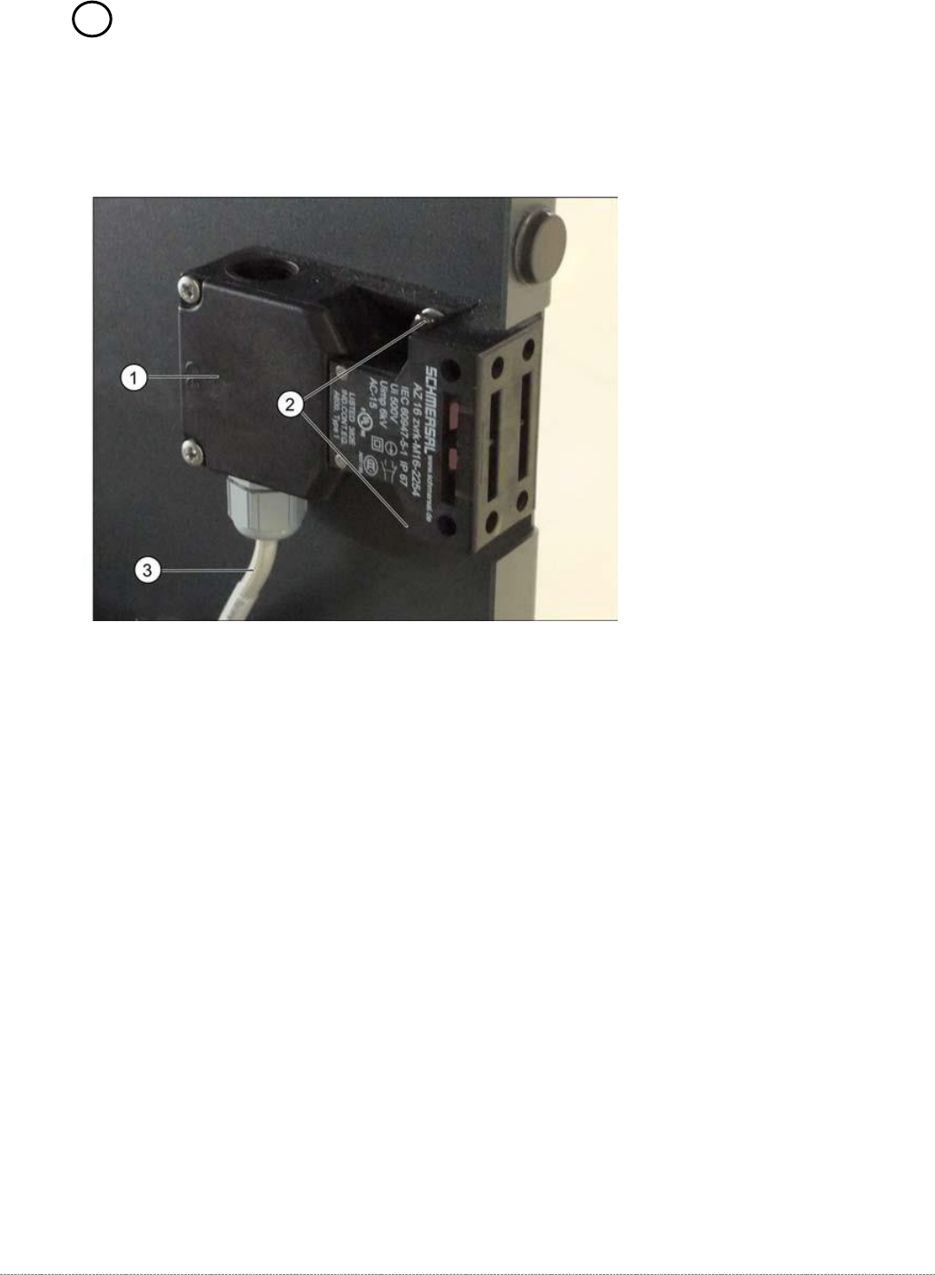
3.7.11 13 Safety Switch
Spare Part
• Safety switch, closed (safety switch with cable) [03062919-xx]
Removal / Installation
➢ Mark the installation position of the safety switch (1) at the two fastening screws (2) with
slots.
➢ Loosen the two fastening screws (2) and remove the safety switch (1).
➢ Unthread the connection cable (3) as far as the control unit back plane..
The connection cable has two separate connections:
• Unplug the connection cable at terminal strip x12a on the control unit back plane.
• Unplug the connection cable from the safety loop.
➢ Fit the new safety switch at the marked installation position.
➢ Restore the electrical connection and fix the connection cable into place.
Settings
➢ Make sure that the door contact engages properly. If necessary, correct the installation
position at the slots.
➢ Check that the safety switch switches reliably at the docked WPC.
Service Manual Internal WPC5 / WPC6
Page 3-100
3.7.12 Sensor 4a / 4b Crash Light Barrier Feed axis vs. Tower
Spare Part
• Crash Light Barrier Feed axis vs. Tower [03056927-xx]
Removal / Installation
WARNING
Special adjustmend necessary
After exchange of the Light barrier, accurate adjustments have to be done, using the „Adjustment
and testing jig WPC4-6 compl.“ [03093396-01].
This work has to be done by trained people (best SIPLACE Service).
See 5.6 Setting the crash light barrier on the tower [
➙
5-165]
NOTICE
Spare Part
The transmitter and receiver of the relevant crash light barrier are stocked as one spare
part with one part number.
Depending on the error occurring, you may need to replace the transmitter and receiver
together.
2
2