00197471-03_Service Manual Internal WPC5_6, EN_01-2019.pdf - 第36页
Service Manual In ternal WPC5 / WPC6 Page 3- 36 Re moval / Installation The load unit drive m otor is located under the base plate of the load unit. ➢ Remo ve the cov er on the load unit (see "3.5. 1.1 Remov e the…
Service Manual Internal WPC5 / WPC6
Page 3-35
3.5.2 Replace the Load Axis Drive Motor
Spare Parts
When replacing the drive motors of the WPC5 and WPC 6, it is, with immediate effect,
necessary to take note of the version / item number of the motor, as the successors are not
100% compatible.
Because it is not permitted to install a mixture of new motors in a WPC, the old drives continue
to be available as replacements!
As a result of this incompatibility, the version of the entire WPC was changed when the new
drives were introduced.
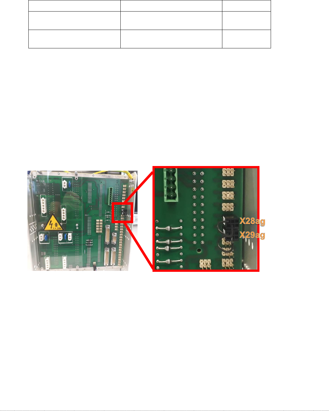
NOTE
At the rear of the control module on WPCs with new motors, a jumper must be fitted to
connector X29ag (changed motors) in addition to jumper X28ag (detection of 45 mm
component height).
Additional Information
The incompatibilities relate to the temperature sensors on the motors.
Minimum Firmware version 40A (WPCHNG_0051040A.BHX) is required to operate the new
motors in the WPC5 / WPC6.
Firmware Version 40A is available as of station software SIRIO 710.0.
If a "WPC5 900-950mm / Standard" [03067619-04], or a "WPC6 900-950mm" [03067618-04]
with new motors is to be fitted to a SIPLACE placement machine with a version of the SIRIO
software < 710.0, you should note the following:
- Any prompt by the station software to download the WPC firmware must be ignored.
- The station software must be upgraded to a version ≥ 710.0.
- If an earlier version of the WPC firmware is (inadvertently) downloaded, the WPC stops and
a temperature error message is issued.
WPC – Type / Version
Spare Part – Name
Part No.
„WPC6 900-950mm“
[03067618-03]
"Servo motor 1FK7022-5AK71-
1AH3-Z S52"
[03052813-xx]
„WPC6 900-950mm“
[03067618-04]
“Servo motor 1FK7022-5AK74-
1AH3-Z + S52”
[03161141-xx]
Service Manual Internal WPC5 / WPC6
Page 3-36
Removal / Installation
The load unit drive motor is located under the base plate of the load unit.
➢ Remove the cover on the load unit (see "3.5.1.1 Remove the Cover on the Load Unit"
[➙ 3-33]).
➢ Loosen the belt tension of the load axis (see "3.5.1.4 Loosen the Tension of the Load Axis
Drive Belt" [➙ 3-34]).
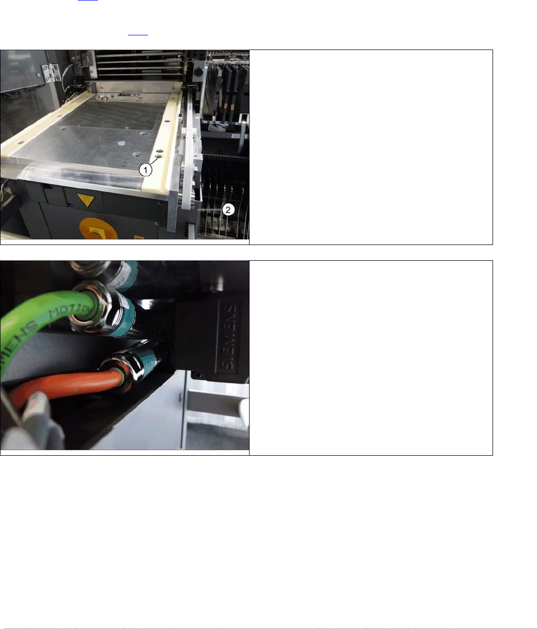
➢ Loosen the screws fastening the motor to the base
plate and the plastic rail (1).
➢ Pull the motor a little to the front, until you have
access to the electrical connections on the left side.
➢ Loosen the two screws fastening the electrical
connections.
⇨ X1 orange cable = power cable
⇨ X2 green cable = control cable
➢
Remove the motor. Make sure that the belt is not
bent or damaged.
Service Manual Internal WPC5 / WPC6
Page 3-37
➢ Fasten the new motor to the motor flange and follow the instructions for removal in reverse
order.
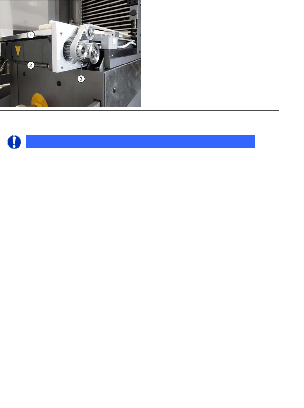
➢
Support the motor from below and loosen the
screws fastening the motor flange at the points
marked 1 to 3..
NOTICE
Screw joints difficult to loosen
Each screw joint has an O-ring seal. This can make opening the screw joint difficult.
Use a pair of water pump pliers to help you unscrew the connection.
Make sure that the O-rings do not fall out of the screw joint and that they are not damaged.