00197471-03_Service Manual Internal WPC5_6, EN_01-2019.pdf - 第87页
Service Manual In ternal WPC5 / WPC6 Page 3- 87 Removal / Install ation LB Type 1 ➢ Loosen the two fasten ing screws (1) for the re levant sensor (transm itter or receiver) on the mounting bracket (2). ➢ Loosen the scr…
Service Manual Internal WPC5 / WPC6
Page 3-86
Tools / Equipment
Example:
„
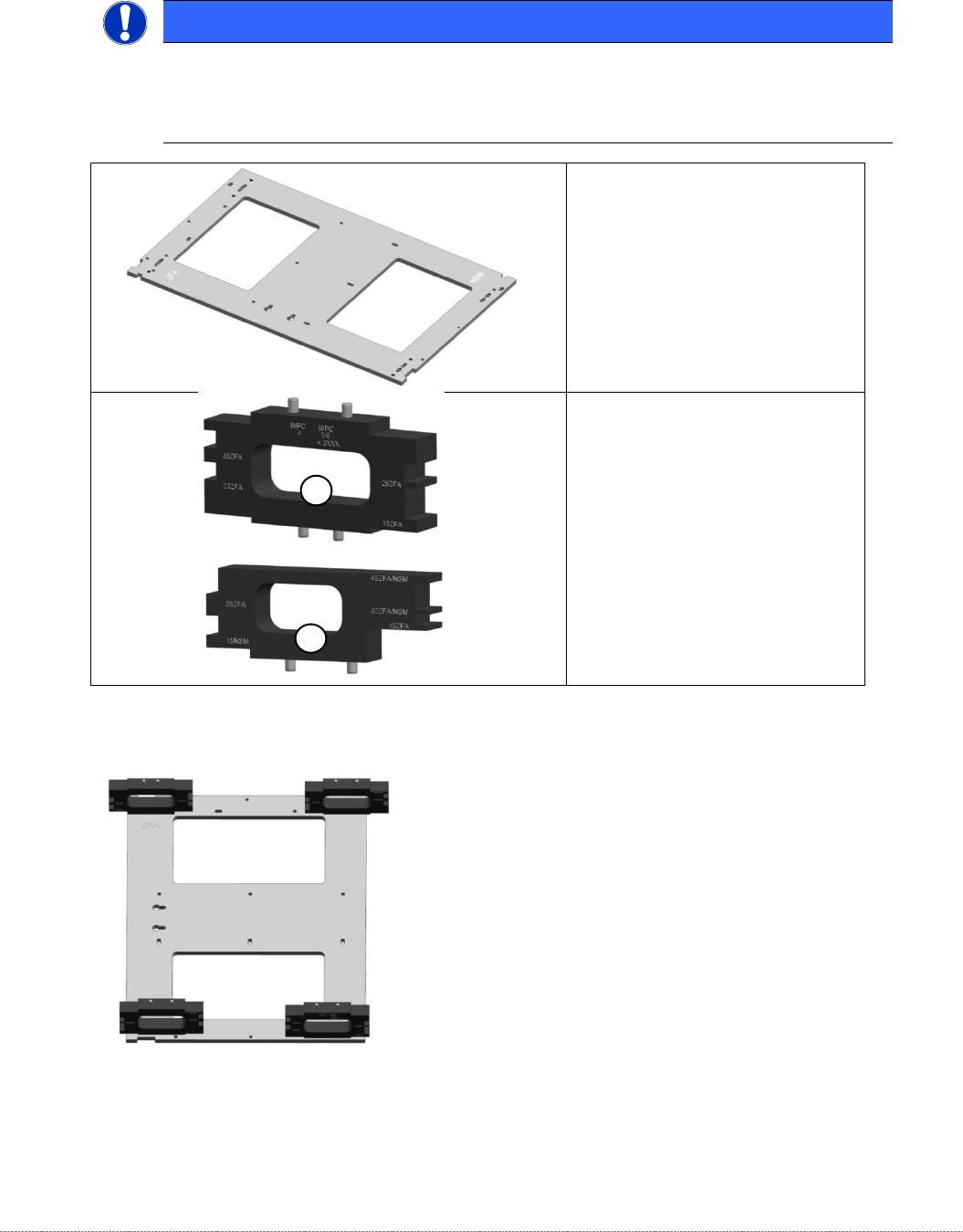
Jig for WPC4-6 base plate
“
[03073064-02] with
„
mounting aid WPC 4-6 old LB
“
[03110476-xx]; the aid can be used
on 4 different positions.
NOTICE
Simplified mounting
To bring the sensor easy into the right position, you can use the „Jig for WPC4-6 base
plate“ [03073064-01], together with the corresponding Mounting aid.
•
„Jig for WPC4-6 base plate“
[ 03073064-02]
1) „Mounting aid WPC4-6 old LB“
[03110476-xx]
for all WPC4, as well as WPC5
and WPC6 up to serial no.
3xxx-
2) “Mounting aid WPC6 HC cpl.“
[03110969-xx]
for all WPC5 and WPC6 from
serial no. 3xxx-
1
2
Service Manual Internal WPC5 / WPC6
Page 3-87
Removal / Installation
LB Type 1
➢ Loosen the two fastening screws (1) for the relevant sensor (transmitter or receiver) on the
mounting bracket (2).
➢ Loosen the screws fastening the cable fixtures (3) and unthread the light barrier cable.
➢ Remove the black plastic guide from the left side of the feed axis, so that the connectors and
cables can be threaded in and out.
➢ The cables are run from the right-hand side, along the underside of the feed axis to the left-
hand side. From there, they are run together with the cables from the left side to the back
plane of the control unit.
➢ Loosen the cable clamps and remove the cable ties.
➢ Unthread the connection cable as far as the control unit back plane and unplug it from the
terminal strip.
➢ Fit the new sensor on the mounting bracket (2).
➢ Align the sensor parallel to the mounting bracket (2).
➢ Restore the electrical connection and fix the connection cable into place.
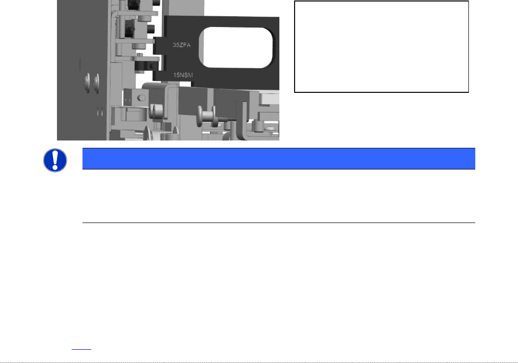
➢ Move the „Jig for WPC4-6 base plate“ [03073064-01] with the corresponding mounting aid to
the position, where the Light barrier has to be made on.
➢ Place the photocell only slightly to the mounting aid and tighten the screw for mounting the
angle at the WPC manually first, so that they can adjust as the adjustments even then.
Settings
➢ Set the crash light barriers. See "3.7.7
Adjusting the Crash Light Barriers for Component height
"
[➙ 3-91].
NOTICE
Use of the mounting aids
Place the corresponding light barrier from the top onto the corresponding step of the aid.
Take care, that the mounting aid is laying flat on the base plate.
The „Mounting aid WPC 4-6 old LB“
[03110476-xx] has pins on 2 sides, to be
positioned on the base plate.
So it can be placed on the base plate in 4
different orientations.
The different heights are labeled directly
beside the corresponding step on the jig
Service Manual Internal WPC5 / WPC6
Page 3-88
Removal / Installation
LB Type 2
➢ Remove the two screws (1) of the respective sensor (transmitter or receiver) to the mounting
bracket (2).
➢ Loosen the screws on the cable clamp (3) and unthread the fibre optic cable.
➢ Remove the black plastic guide from the left side of the feed axis, so that the connectors and
cables can be threaded in and out.
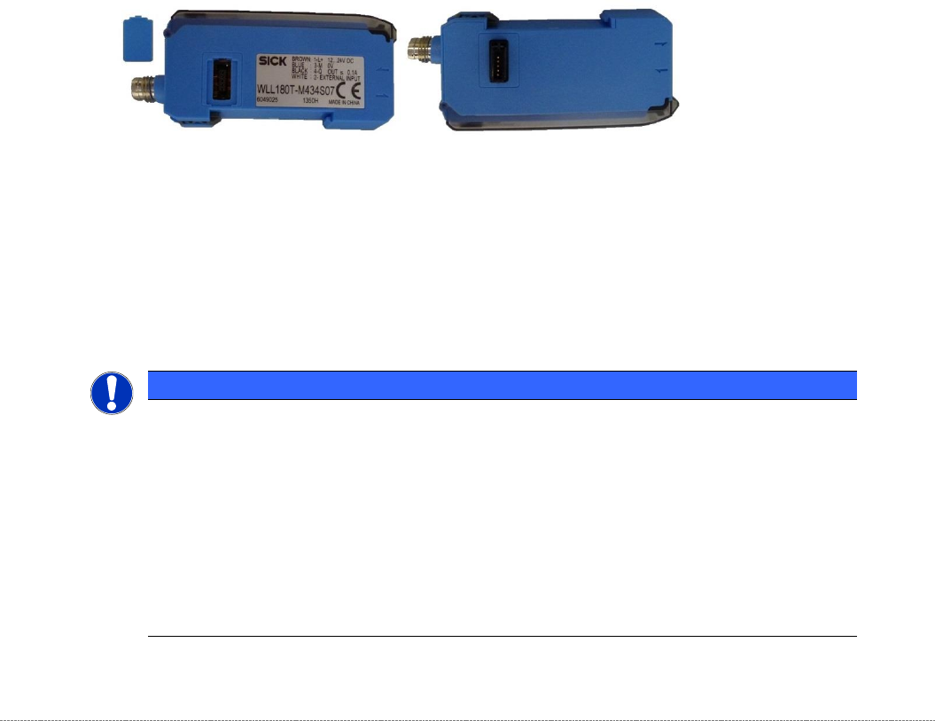
➢ Remove the cover from the feed axis .
The control units of the three light sensors are located under this cover (4), snapped on a
DIN rail.
In the control units there are 2 different part numbers.
If several of these units used, as always a master unit must be present:
"Fiber-optic sensor WLL180T-M vorprog Sxa" [03093294-01]
The "Follow-units" are plugged into the master unit and each "Follow-unit" can turn another
are infected.
"Fiber-optic sensor WLL180T-F vorprog Sxa" [03093295-01]
➢ The 2 pieces " Fiber-optic sensor WLL180T for the LS TYPE 2 in the NSM module are
located in the control rack of the WPC , snapped on a newly added top hat rail.
➢ From the control unit, the connecting cable is going down to the terminal block on the
backplane of the control slot, via a round plug.
NOTICE
Change of a control unit
The default setting of a new control unit is set to "D on" (Dark on), means active with an interrupted light beam.
However, for the WPC "L on" (Light on), means active with non-interrupted light beam, is required. .
When replacing a controller, therefore, the following settings must be made:
➢ Press Mode button for 3 sec.,
➢ Press Mode again, „d on“ is flashing,
➢ Switch to „L on“ with right cursor,
➢ Press Mode again,
➢ Restart the WPC.