00197471-03_Service Manual Internal WPC5_6, EN_01-2019.pdf - 第123页
Service Manual In ternal WPC5 / WPC6 Page 4-123 4.1.5 Teaching the Load Axis Offset Point You o nly n eed to t each the off set p oint if you have c hange d the z ero p oint positi on (se e "4. 1.2 Teac hing th e …
Service Manual Internal WPC5 / WPC6
Page 4-122
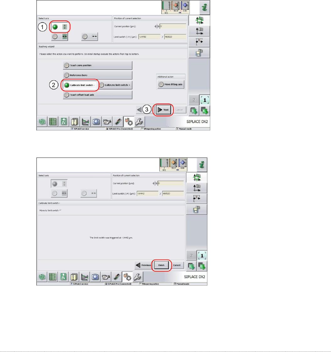
4.1.4 Calibrating the Limit Switch
The plus and minus position of the limit switches need to be calibrated.
➢ Remove all waffle-pack tray carriers (WPTC) from the WPC.
➢ Select the lifting axis (1).
➢ Select the function
Calibrate limit switch
- (2).
➢ Select
Next
(3).
Calibrating the limit switch -
➢ Confirm the new position at which the limit switch triggers with
Finish
.
Calibrating the limit switch +
➢ Select the lifting axis (1).
➢ Select the function
Calibrate limit switch +
and continue with the same procedure as that
used for calibrating the limit switch.
Service Manual Internal WPC5 / WPC6
Page 4-123
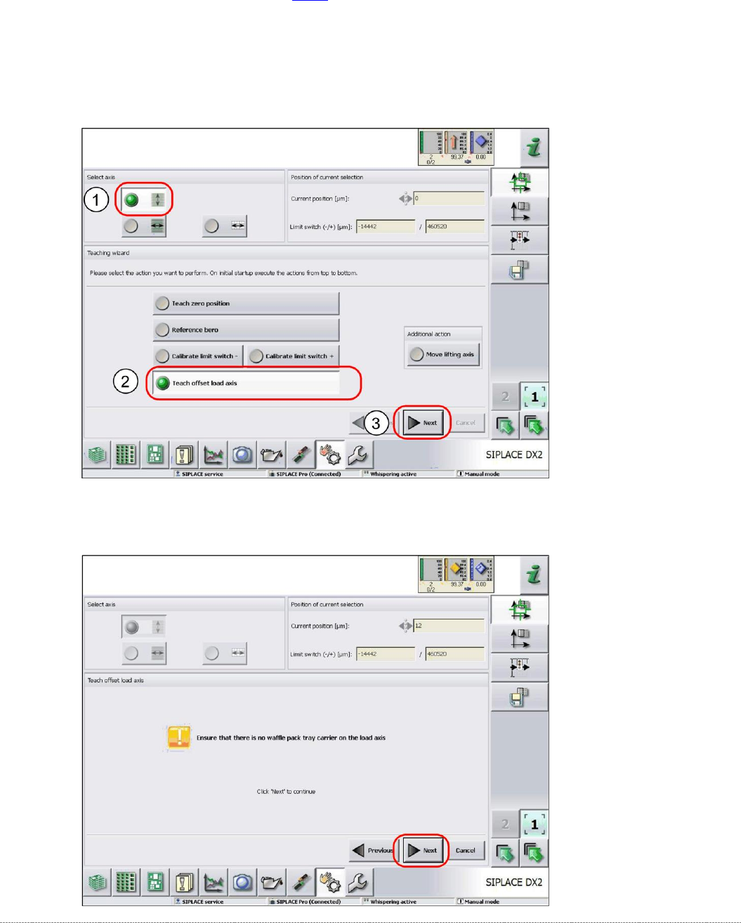
4.1.5 Teaching the Load Axis Offset Point
You only need to teach the offset point if you have changed the zero point position (see "4.1.2
Teaching the Zero Point Position" [
➙
4-118]).
➢ Remove all waffle-pack tray carriers (WPTC) from the WPC.
➢ Select the lifting axis (1).
➢ Select the function
Teach offset load axis
(2).
➢ Select
Next
(3).
➢ Follow the instruction shown and continue with
Next
.
Service Manual Internal WPC5 / WPC6
Page 4-124
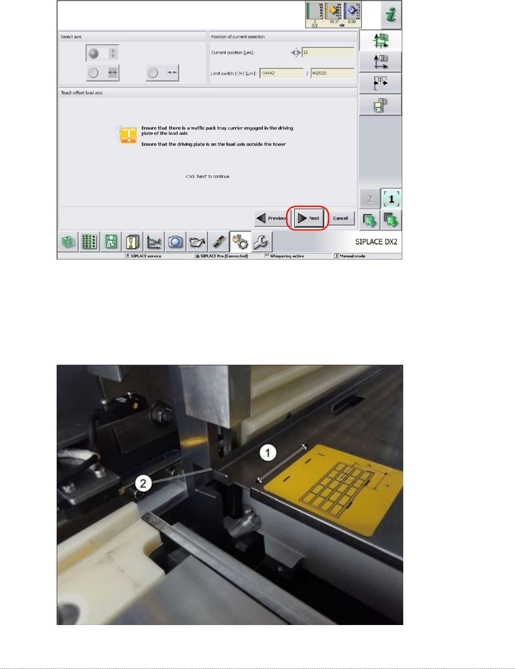
➢ Follow the instruction shown and continue with
Next
.
➢ Place the „Jig for WPC4-6 base plate“ [03073064-01] (or a WPTC) (1) on the sliding rail of
the load axis.
➢ Push the gauge into the tower (2).
➢ Make sure that the gauge can be moved along the sliding rail smoothly.