00197471-03_Service Manual Internal WPC5_6, EN_01-2019.pdf - 第30页
Service Manual In ternal WPC5 / WPC6 Page 3- 30 3.4.7 Replace the Linear Guide 2SRS9MUU+865LM Spare Part • Linear gu ide 2SRS9MUU+865LM [0 3047013- xx] Preparations ➢ Move the tower into the r efill position. ➢ Remove …

Service Manual Internal WPC5 / WPC6
Page 3-29
➢ Push the driver unit fully into the tower.
➢ Push the two setting gauges (1) + (2) under the toothed belt, at a distance of 360 mm.
⇨ The teeth of the toothed belt (3) must lie on the setting gauge.
➢ Press the large setting gauge downwards with a suitable object or with your finger, so that
the toothed belt lies on the gauge (5).
➢ Adjust the belt tension. To do this, gently pull the toothed belt or tap it with an Allen wrench,
so that it starts swinging and then measure the value with the belt tension measuring device.
⇨ Setting value: The belt tension must be 90 Hz +/-5 Hz.
Service Manual Internal WPC5 / WPC6
Page 3-30
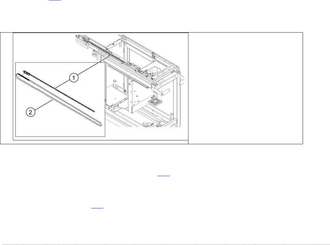
3.4.7 Replace the Linear Guide 2SRS9MUU+865LM
Spare Part
• Linear guide 2SRS9MUU+865LM [03047013-xx]
Preparations
➢ Move the tower into the refill position.
➢ Remove all waffle pack tray carriers (WPTCs) from the tower.
➢ Move the tower downwards.
⇨ Check sensors and functions ⇨ Check sensors and functions of specific components ⇨
⇨ Location ⇨ Check functions for WPC ⇨ Move into transport position.
➢ Undock the WPC from the SIPLACE machine and move it to a suitable position for service
work.
➢ Switch the WPC off at the main switch.
➢ Unplug from the power supply and secure the WPC to prevent unauthorized reactivation.
➢ Remove the cover of the NSM module (see "3.5.1.1 Remove the Cover on the Load Unit" [
➙ 3-33]).
Removal / Installation
➢ Proceed as if you were replacing the toothed belt of the feed axis (see "3.4.5 Replace the
Feed Axis Toothed Belt [03047690-xx]" [➙ 3-25]) and move the belt to a position which
allows you to loosen the linear guide screws.
➢ Remove the driver assembly on the WPC 6 (see "3.5.5 Replace the Driver Assembly
[03053436-xx]" [➙ 3-43]).
(1) Linear guide 2SRS9MUU+865LM
(2) Toothed belt for the drive
Service Manual Internal WPC5 / WPC6
Page 3-31
➢ Remove all screws from the guide rails and lift off the rails.
➢ If necessary, also remove the reference sensor and the load axis crash light barriers.
➢ Clean the contact surface with ethanol, before inserting the new guide rail.
➢ Position the new guide rail in place, press it against the stop edge and then loosely tighten
the screws. Make sure that the screws are centered in the holes.
➢ Tighten the screws. Start in the middle. There is no need to observe a specific torque. You
do not need to seal the screws with locking varnish.
➢ Make sure that the whole length of the guide rail lies against the stop edge.
➢ Fit the clamping unit.
There is no need to observe a specific torque. You do not need to seal the screws with
locking varnish.
➢ Continue by following the removal procedure in reverse order (see "3.5.5 Replacing the
Driver Assembly [03053436-xx]" [➙ 3-43] for WPC 6 and "3.4.5 Replacing the Feed Axis
Toothed Belt” [03047690-xx]" [➙ 3-25]).
See also...
@
3.4.4.1
Align the Driver Unit [➙ 3-24]
@
3.4.6
Setting the Feed axis Belt Tension [
➙
3-28]
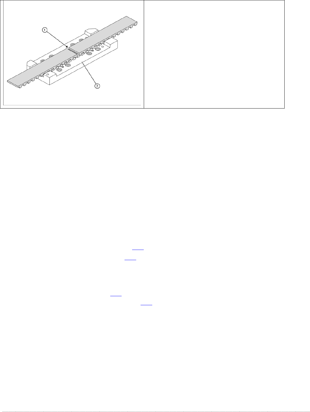
➢ Loosen the toothed belt clamping unit (1) from
the guide carriage.
➢ To do this, remove the 8 screws at 2.