00197471-03_Service Manual Internal WPC5_6, EN_01-2019.pdf - 第91页
Service Manual In ternal WPC5 / WPC6 Page 3- 91 3.7.7 A djusting the Crash Light Barrie rs for Component height Tools / Equip ment Measurement se tup and procedu re ➢ Br ing the „ J ig for WPC4-6 b ase plate “ [0307306…

Service Manual Internal WPC5 / WPC6
Page 3-90
Settings
➢ Set the crash light barriers. See "3.7.7
Adjusting the Crash Light Barriers for Component height
"
[➙ 3-91].
NOTICE
Notice the direction of the light beam in the NSM module
In NSM module (at the loading axis) for the standard BE-height (15mm), a light barrier LS TYPE 1 is used.
The recipient of this photocell is on the left side (as seen in the direction to the feed axis).
When mounting the other two BE-heights (32 and 35, or 45mm) from the LS TYPE 2, attention must be paid to
the direction of the light beam. The light output has to be on the left side as well, so that the light beam can not
interfere with the recipient of the BE-height 15mm (LS TYPE 1).
You can simply swap the two fibre optic cables on the control unit if you need to change the light’s direction.
Service Manual Internal WPC5 / WPC6
Page 3-91
3.7.7 Adjusting the Crash Light Barriers for Component height
Tools / Equipment
Measurement setup and procedure
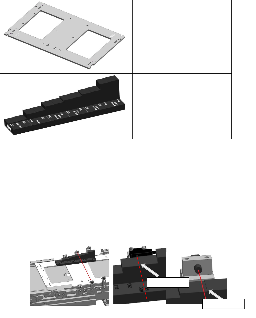
➢ Bring the „Jig for WPC4-6 base plate“ [03073064-02] with the mounted "Adjustment-Jig
crash-LS-WPC4-6 (step)” [03093895-02] in position.
The “step gauge” can be plugged at 3 positions on the base plate.
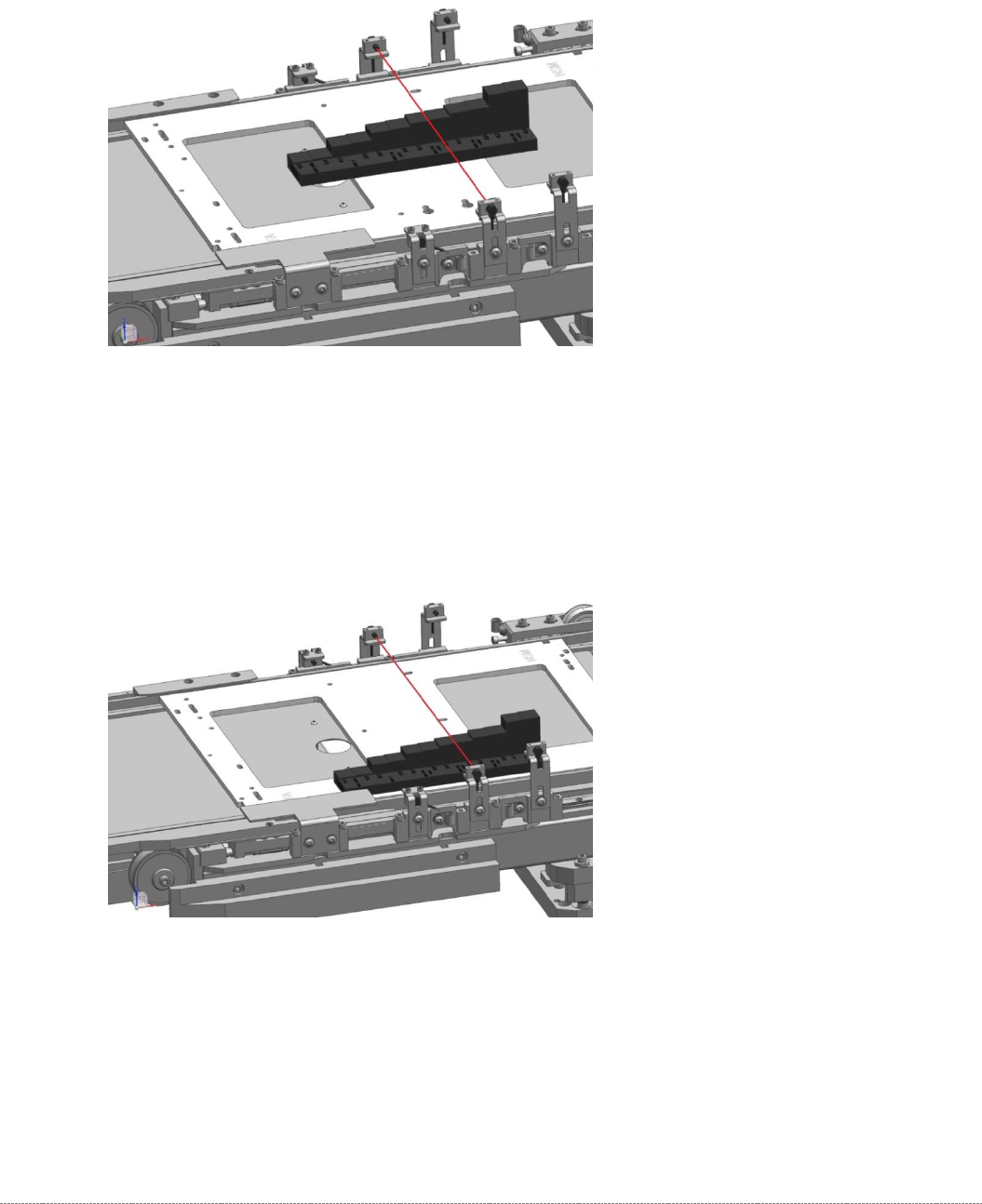
You start at the position left on the feed axis. This is directly in front of the photocell, so you
can see the position that they should reach well.
➢ Move the base plate with the “step gauge” slowly forward on the feed axis.
The Light barrier must be exactly at the level of the respective stages pair position (e.g.
29mm below).
• „Jig for WPC4-6 base plate“
[03073064-02]
• Adjustment-Jig crash-LS-WPC4-6
(step) [
03093895-02]
Switching stage
Switching stage
Service Manual Internal WPC5 / WPC6
Page 3-92
➢ Now plug the "Adjustment-Jig crash-LS-WPC4-6 (step)” [03093895-01] to the center position
of the base plate.
➢
Move the base plate with the “step gauge” slowly forward on the feed axis.
The Light barrier must be exactly at the level of the respective stages pair position.
.
➢ Now plug the "Adjustment-Jig crash-LS-WPC4-6 (step)” [03093895-01] to the right position
of the base plate.
➢
Move the base plate with the “step gauge” slowly forward on the feed axis.
The Light barrier must be exactly at the level of the respective stages pair position.