00197471-03_Service Manual Internal WPC5_6, EN_01-2019.pdf - 第166页
Service Manual In ternal WPC5 / WPC6 Page 5-166 NOTICE Position of the crash ligh t barrier W hen setti ng the light b arrier, mak e sure that the positions of the transm itter and receiver match. To do this, use a sli…
Service Manual Internal WPC5 / WPC6
Page 5-165
5.6 Setting the crash light barrier on the tower
The gauge is still clamped in level 5 (as described in Section 5.3).
Now attach the gauge for setting the crash light barrier to the baseplate.
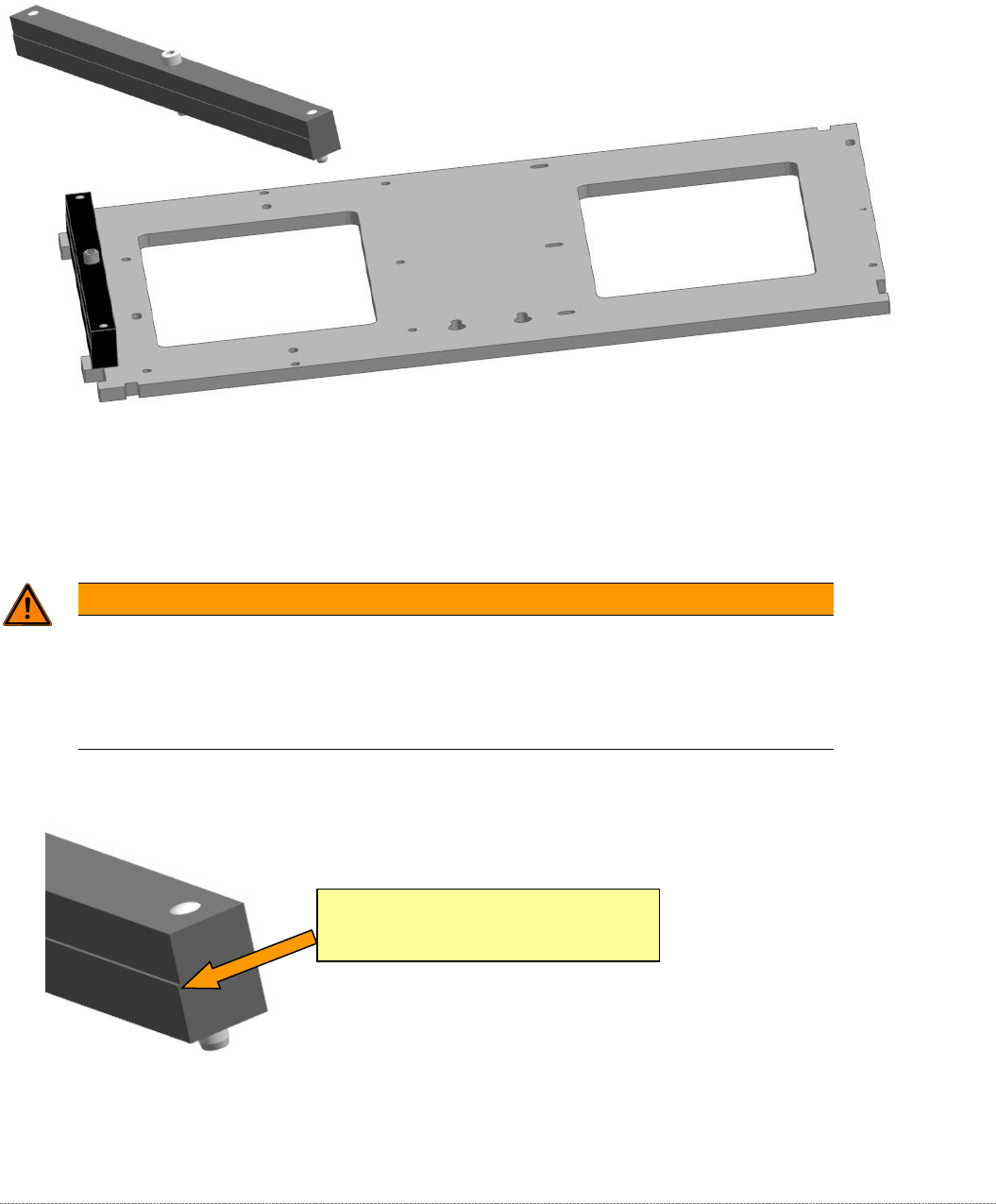
Figure 5.27: Base plate of the gauge with the attachment "Strip for crash light barrier, transfer point, feed axis" [03093816-01].
Move the lifting axis to a position at which the gauge attachment interrupts the beam.
The light barrier must trigger exactly at the transition to the edge of the gauge attachment.
WARNING
Unsafe mode
You must enable "unsafe mode" in order to step the lifting axis.
You should therefore only move the lifting axis with extreme care and in small, easily
monitored steps.
Set the light barrier so that the beam is interrupted exactly at the edge of the gauge.
Figure 5.28: Trigger point on "Strip for crash light barrier, transfer point, feed axis" [03093816-01]
If necessary, move the light barrier by releasing the screw marked above on the side of the tower
cover.
Switching edge on the gauge
"Strip for crash light barrier, transfer point, feed
axis" [03093816-01]
Service Manual Internal WPC5 / WPC6
Page 5-166
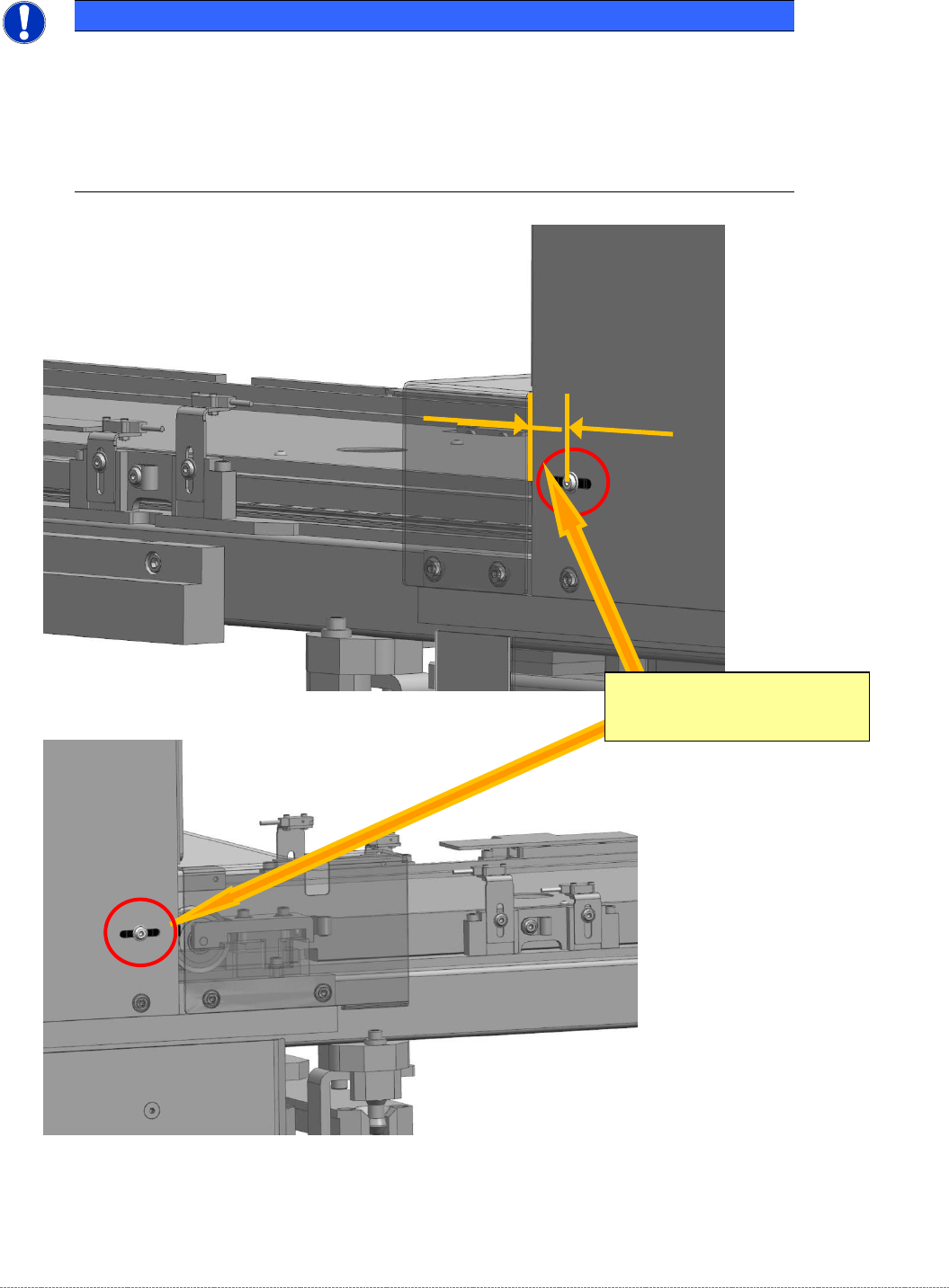
NOTICE
Position of the crash light barrier
When setting the light barrier, make sure that the positions of the transmitter and receiver
match. To do this, use a sliding gauge to measure the exact position of the front edge of
the tower cover with respect to the center of the screw on both sides. This gives the
rough position.
Adjustment of the final x/10 mm can then be done on one side.
Figure 5.29: Setting the crash light barrier at the transfer point to the feed axis
Figure 5.30: Setting the crash light barrier at the transfer point to the feed axis, right
Switching edge on the gauge
"Strip for crash light barrier, transfer
point, feed axis" [03093816-01]
Service Manual Internal WPC5 / WPC6
Page 5-167
5.7 Setting the deflector at the flap to the loading axis
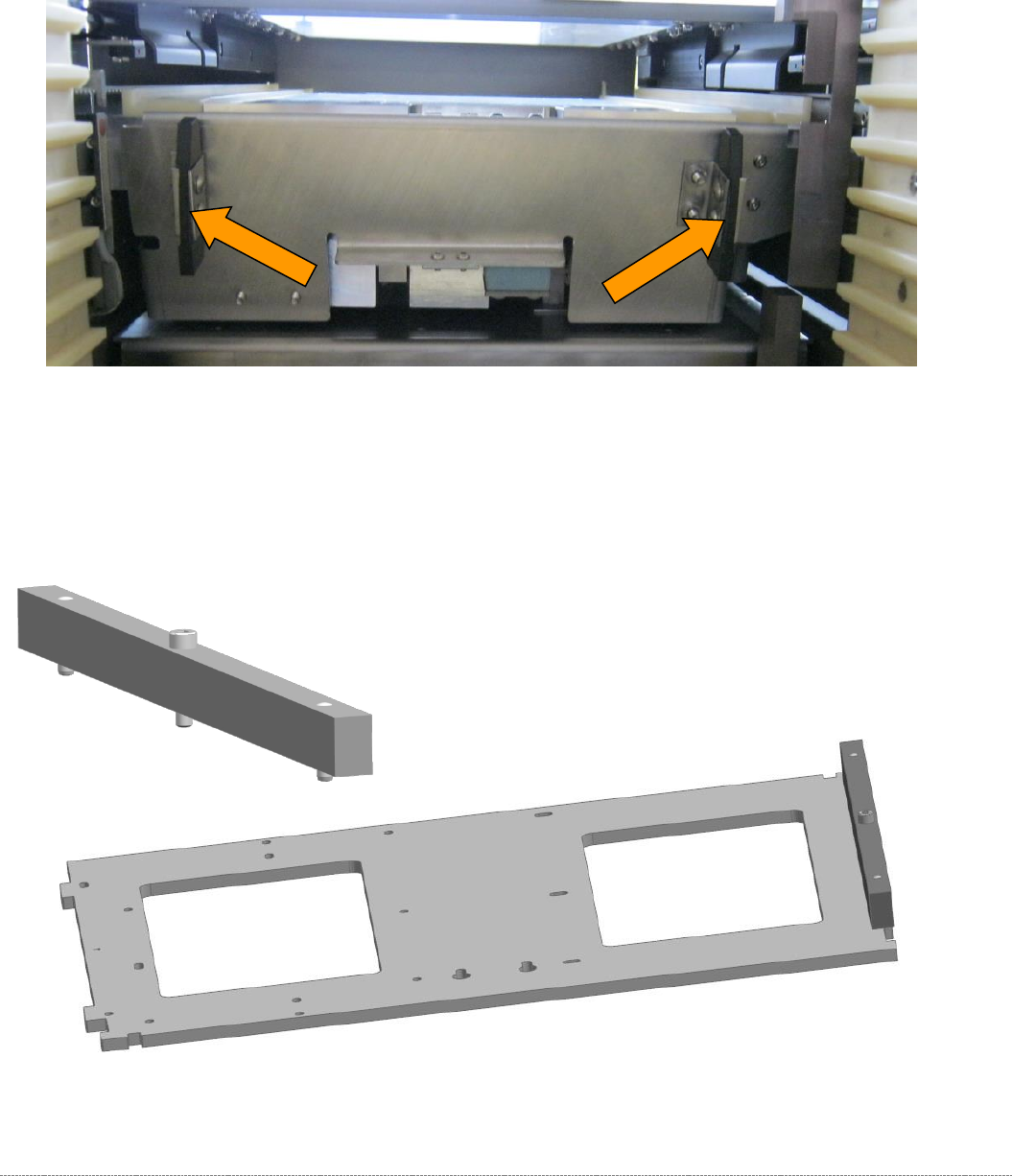
2 plastic deflectors are installed at the protective flap between the tower and the non-stop module
(loading axis).
These deflectors are also used to align the waffle pack tray carriers in the tower.
Figure 5.31: Deflectors at the protective flap.
The gauge is still clamped in the tower in the position described above.
The protective flap is closed, i.e. in the top position.
To make this setting, attach the "Strip for stopper flap, complete" [03093815-xx] to the baseplate..
Figure 5.32: Base plate of the gauge with the deflector setting gauge attachment.