00197471-03_Service Manual Internal WPC5_6, EN_01-2019.pdf - 第149页
Service Manual In ternal WPC5 / WPC6 Page 5-149 • Plug the „ Gauge bas e setting base plate position“ [0 3110862- xx ] on the base plate. • Move the gauge into the tower, until the „Gauge base setting base plate positi…
Service Manual Internal WPC5 / WPC6
Page 5-148
5.3 Positioning and securing the gauge
NOTICE
Removing carrier plates from the tower
Remove all carrier plates from the tower. Only the gauges are required for the settings
described below.
• Remove all additional gauges from the baseplate and only use the "Jig for WPC4-6 base
plate" [03073064-01].
NOTICE
Using 2 base plates
In order to facilitate setting the guide rails in particular, it is recommended that you use
2x "Jig for WPC4-6 base plate" [03073064-01] to avoid the need to move a single gauge
from the top to the bottom.
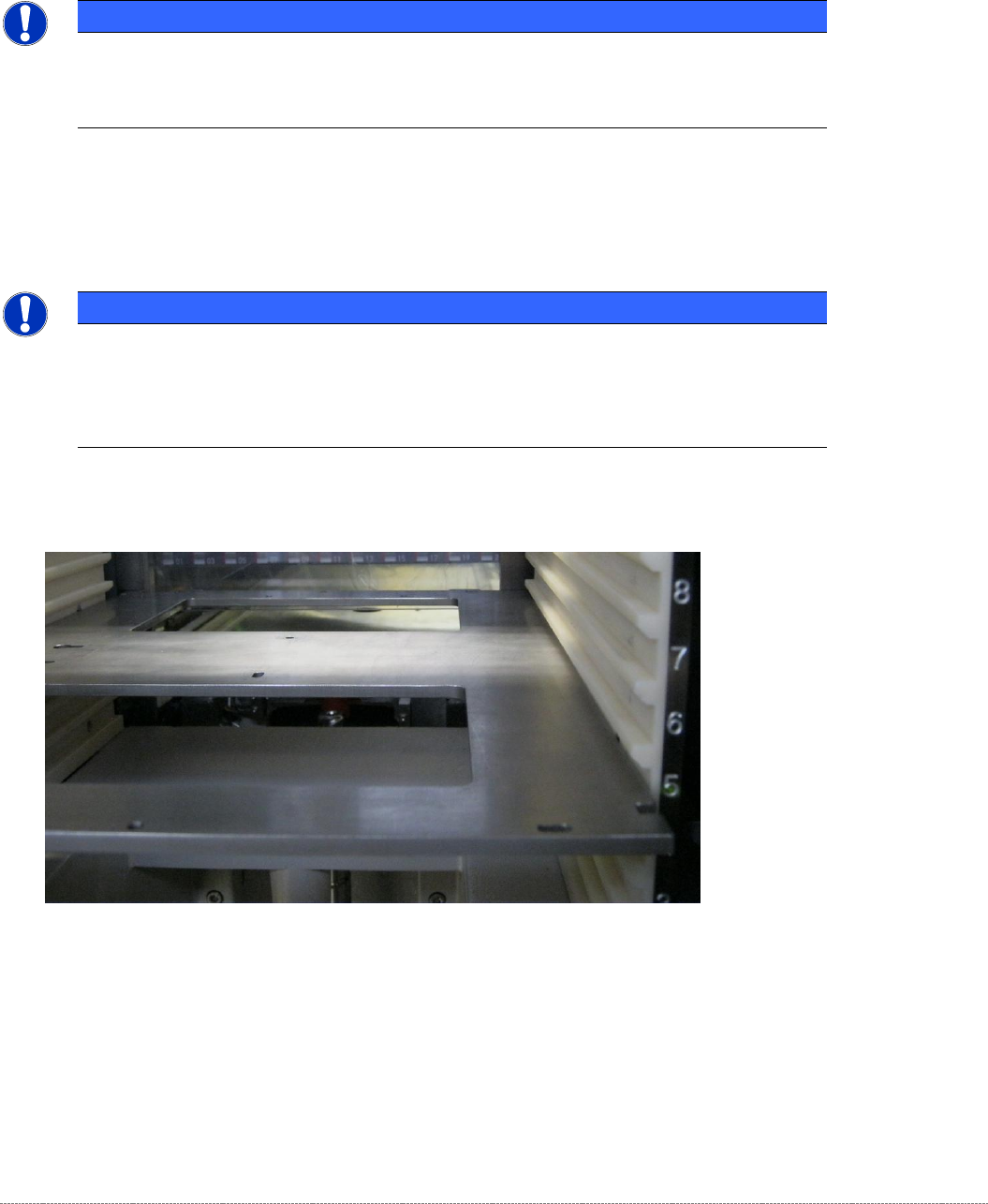
• Position the gauge in Level 5.
Figure 5.1: Positioning the gauge in Level 5.
• Step the tower (lifting axis) downwards until the gauge is at the same height as the linear
guide rails of the lifting axis.
Service Manual Internal WPC5 / WPC6
Page 5-149
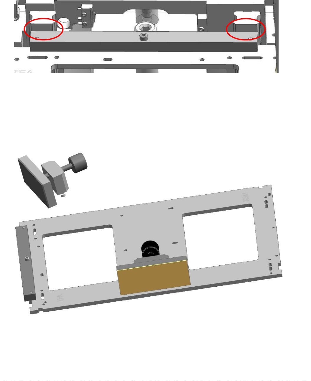
• Plug the „Gauge base setting base plate position“ [03110862-xx] on the base plate.
• Move the gauge into the tower, until the „Gauge base setting base plate position“
[03110862-xx] strikes the guide rails on both sides.
Figure 5.2: Strike the Guide rails of the lifting axis with the “Gauge base setting base plate position” [03110862-01]
• Attach the "clamping readout tower adjust.WPC4-6 cpl." [03093864-01] to the base unit.
The mounting for the clamp on the baseplate is a pair of keyhole slots.
There is no need to tighten the clamp on the baseplate. It is sufficient to tighten the screws
by hand. When the clamp is closed, the attachment is automatically pushed into the end of
the slots.
Figure 5.3: Base plate gauge with clamp attachment.
Service Manual Internal WPC5 / WPC6
Page 5-150
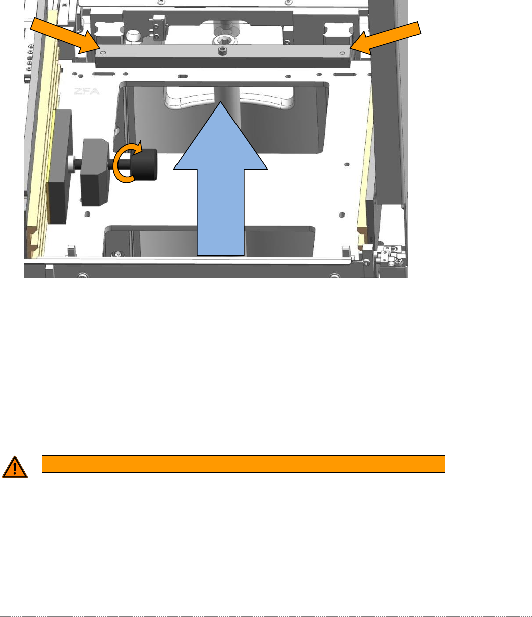
• Now clamp the gauge in level 5 of the tower with the clamp mount "clamping readout tower
adjust.WPC4-6 cpl." [03093864-01].
• Press the gauge onto the front of the guide rails, while you tighten the clamp, so that the
gauge with the addon "Teaching Basic settings. Position base plate" [03110862-xx] rests on
both rails!
Figure 5.4: Base plate gauge with clamp attachment.
• Close the clamp until the built-in overtightening prevention mechanism triggers.
• Now, when the gauge base plate is clamped correctly, remove the "Teaching Basic settings.
Position base plate" [03110862-xx] from the base plate.
WARNING
Do not displace the gauge
Although the gauge is clamped in the tower, it is not clamped tightly.
When you are performing your work, in particular when inserting and removing the addon
gauges, make sure that you do not displace the gauge.
Move the gauge until the
strike with the guide rail.