00197471-03_Service Manual Internal WPC5_6, EN_01-2019.pdf - 第168页
Service Manual In ternal WPC5 / WPC6 Page 5-168 Now move the tower to the position at which the gauge with the attached " Strip for stopper flap, complete" [03093815 - xx ]" , is precisel y in the settin…
Service Manual Internal WPC5 / WPC6
Page 5-167
5.7 Setting the deflector at the flap to the loading axis
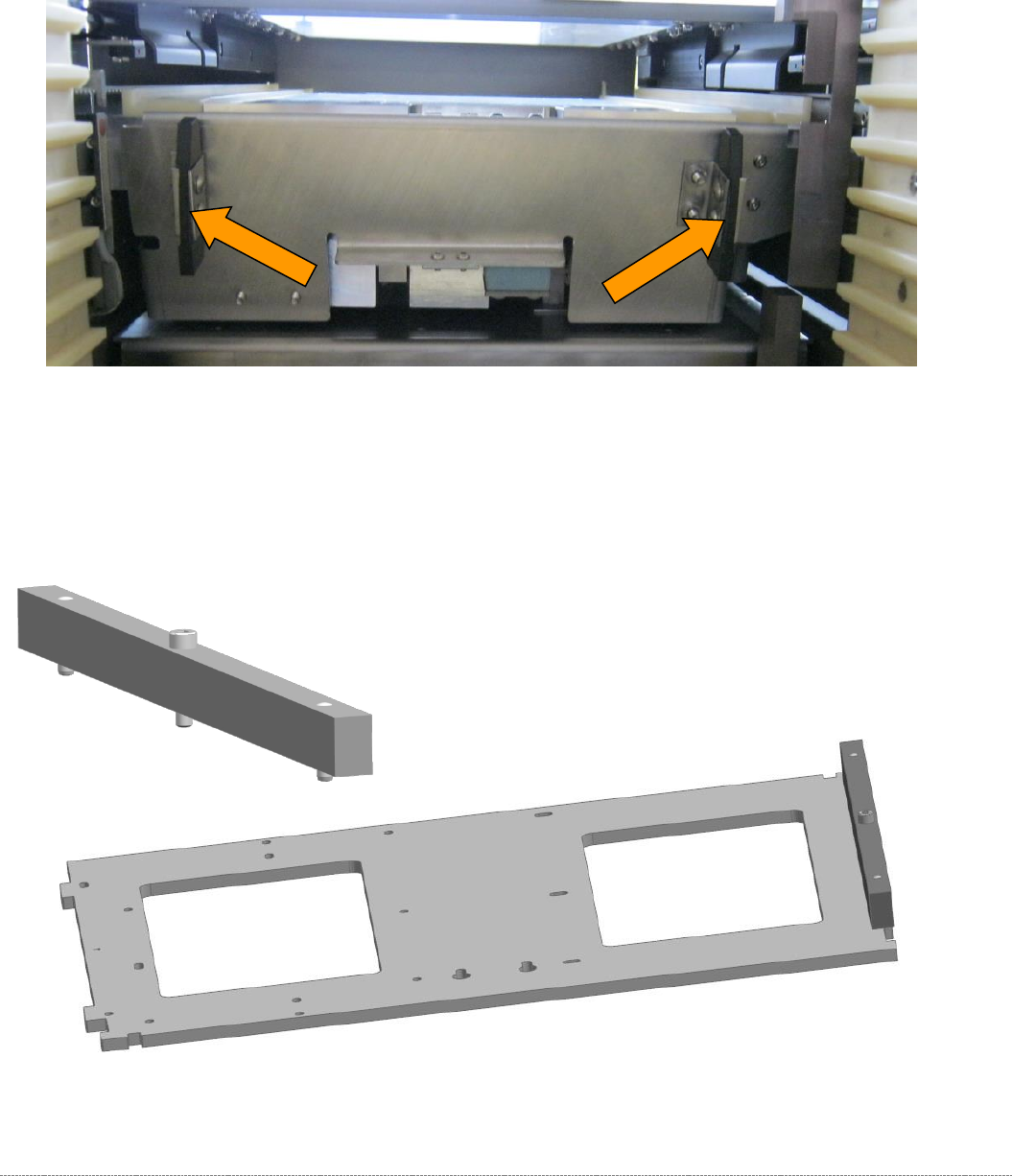
2 plastic deflectors are installed at the protective flap between the tower and the non-stop module
(loading axis).
These deflectors are also used to align the waffle pack tray carriers in the tower.
Figure 5.31: Deflectors at the protective flap.
The gauge is still clamped in the tower in the position described above.
The protective flap is closed, i.e. in the top position.
To make this setting, attach the "Strip for stopper flap, complete" [03093815-xx] to the baseplate..
Figure 5.32: Base plate of the gauge with the deflector setting gauge attachment.
Service Manual Internal WPC5 / WPC6
Page 5-168
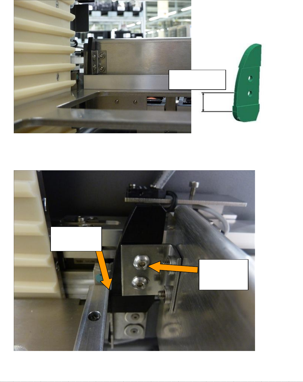
Now move the tower to the position at which the gauge with the attached "Strip for stopper flap,
complete" [03093815-xx]", is precisely in the setting range of the deflectors.
Move the gauge with the strip into the setting range of the deflectors.
Figure 5.33: Setting the deflectors on the safety flap.
Now set the gap to the deflector in such a way that the strip just touches the deflector.
Figure 5.34: Setting the deflectors on the safety flap.
Deflector lightly
touching the
bar.
Screws for
adjusting and
securing the
deflectors.
Setting range on
the deflector
Service Manual Internal WPC5 / WPC6
Page 5-169
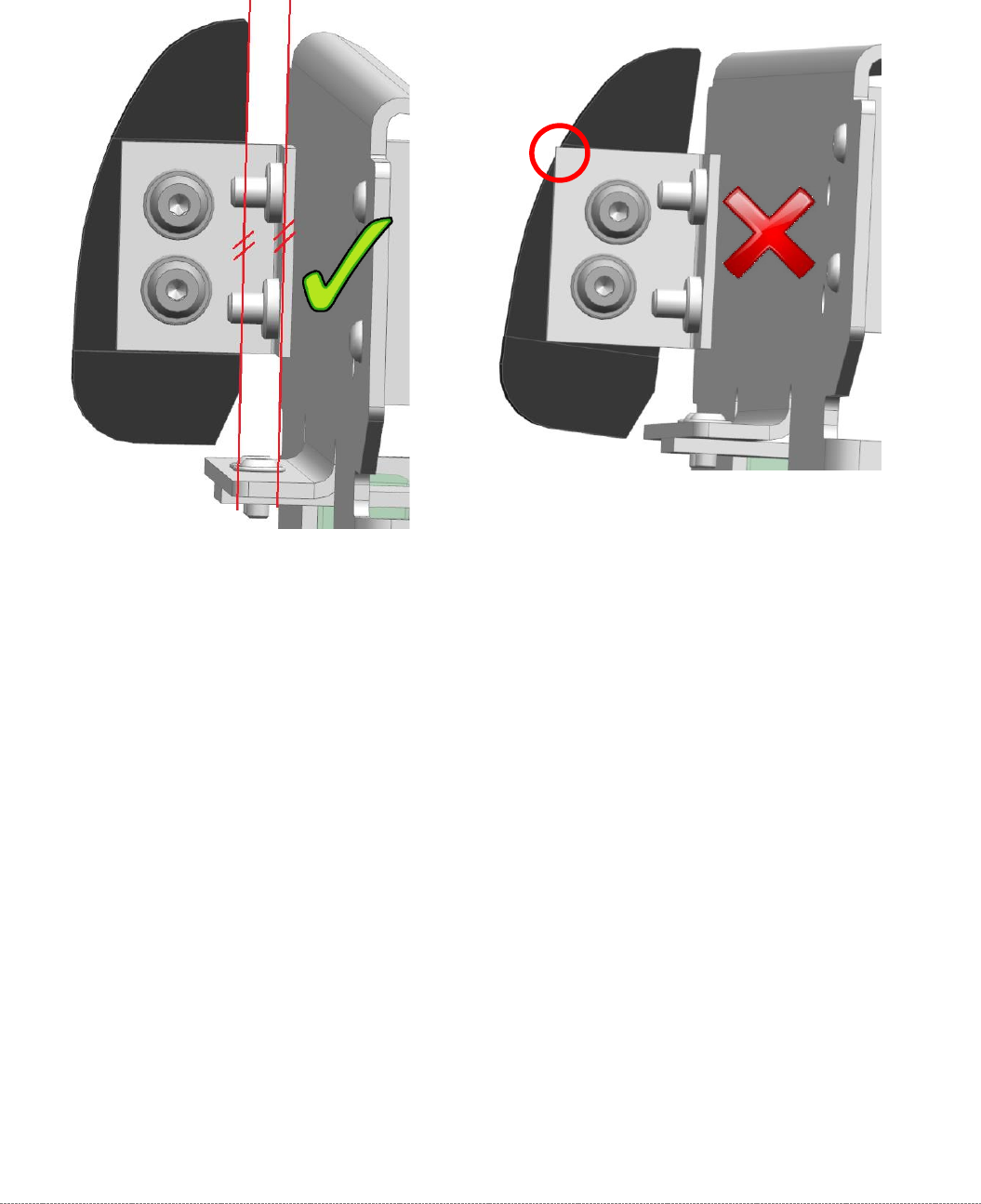
The deflector should always be fitted as parallel as possible to the safety flap.
Pay attention that the black plastic part always covers the metal edge, on which it is mounted, so
that no interfering edge occurs.