00197471-03_Service Manual Internal WPC5_6, EN_01-2019.pdf - 第102页
Service Manual In ternal WPC5 / WPC6 Page 3-102 3.7.13 Sensor 12 Reference Proximity Switch Load axis Spare Part • Reference point prox imity switch load axis [03056947- xx] Removal / Install ation ➢ Loosen the two scr…
Service Manual Internal WPC5 / WPC6
Page 3-101
➢ Mark the exact position of the light barrier on the metal bracket, as well as the position from
the metal bracket on the tower cover.
➢ Loosen the two fastening screws of the Light Barrier Receiver/Sender (1).
➢ The Light Barrier is mounted on a metal bracket, which is set on the Tower Cover with a
screw from outside the cover (2).
➢ Loosen the cable clamps and remove the cable ties.
➢ Unthread the connection cable as far as the control unit back plane and unplug it from the
terminal strip.
The cable is guided on a support plate between Tower and Tower’s Cover and then moved
below the feed axis.
➢ Fit the new crash light barrier at the marked installation position.
➢ Restore the electrical connection and fix the connection cable into place.
Settings
➢ Set the crash light barrier. See "5.6
Setting the crash light barrier on the tower
" [➙ 5-165].
2
Service Manual Internal WPC5 / WPC6
Page 3-102
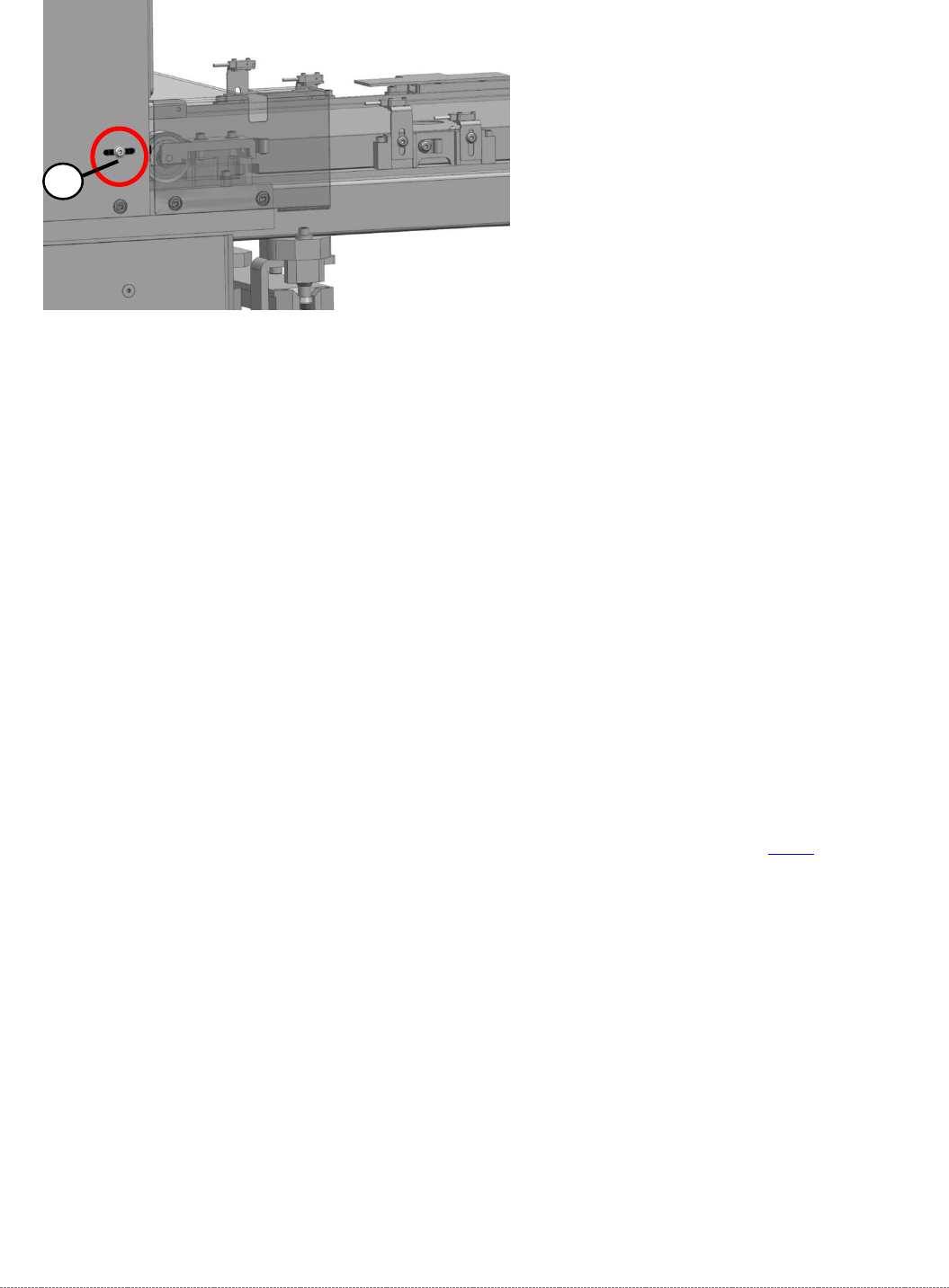
3.7.13 Sensor 12 Reference Proximity Switch Load axis
Spare Part
• Reference point proximity switch load axis [03056947-xx]
Removal / Installation
➢ Loosen the two screws (1) fastening the sensor fixture bracket and unthread the cable.
➢ Unthread the connection cable as far as the control unit back plane and unplug it from the
terminal strip.
➢ Loosen the two screws (2) fastening the sensor to the fixture bracket and then remove the
sensor.
➢ Screw the new sensor to the fixture bracket (2).
➢ Fix the bracket into the tower with the two screws which you removed (1).
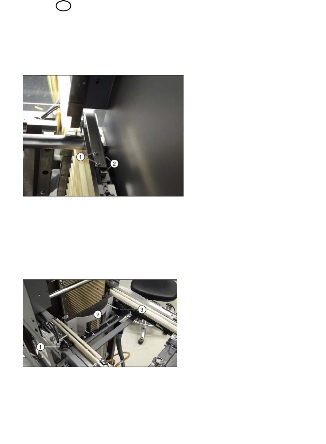
➢ Run the cable out of the tower, under the feed axis and along to the other side (1 to 3) and
up to the back plane of the control unit. Fix the cable into place with cable ties.
➢ Restore the electrical connection and fix the connection cable into place.

Service Manual Internal WPC5 / WPC6
Page 3-103
Settings
➢ Check the function and correct position of the reference sensor. The sensor must trigger
when the driver actuator is just below the sensor. (Reference point).
➢ To do this, open the station software menu
⇨ Sensors and Functions ⇨ Location ⇨ Check functions for WPC ⇨ Advanced functions
.
➢ Enable the feed axis and click on the
Reference bero
button.
The feed axis will be moved so that the driver actuator triggers the reference sensor. The
reference point will be calculated.
The calculated value will be shown and can then be saved with the
Commit
button.
➢ If an error message appears, correct the mechanical position by adjusting the cam on the
driver (see "4.3.3.1 Setting the Driver Cam" [➙ 4-138]) and repeat the measuring process.
➢ Coat the cam fastening screw with locking varnish.
➢ Calibrate the reference proximity switch (see "4.2.3 Reference Proximity Switch (Bero)" [➙
4-129]).