00197471-03_Service Manual Internal WPC5_6, EN_01-2019.pdf - 第90页
Service Manual In ternal WPC5 / WPC6 Page 3- 90 Settings ➢ S et the crash light barr iers . See "3 .7.7 Adjusting the Crash Light Barriers for Component height " [ ➙ 3- 91 ]. NOTICE Notice the direct ion of t…
Service Manual Internal WPC5 / WPC6
Page 3-89
➢ Connect the optical fiber at the corresponding control unit.
With the accompanying cutting tool in the spare part „Fibre optic cable LL3-TV05 2m“
[03092407-xx] you can cut the light guide to the required length.
➢ Mount the new fbre optic cable onto the mounting bracket (2 on 3).
➢ Align the sensor parallel to the mounting bracket (2).
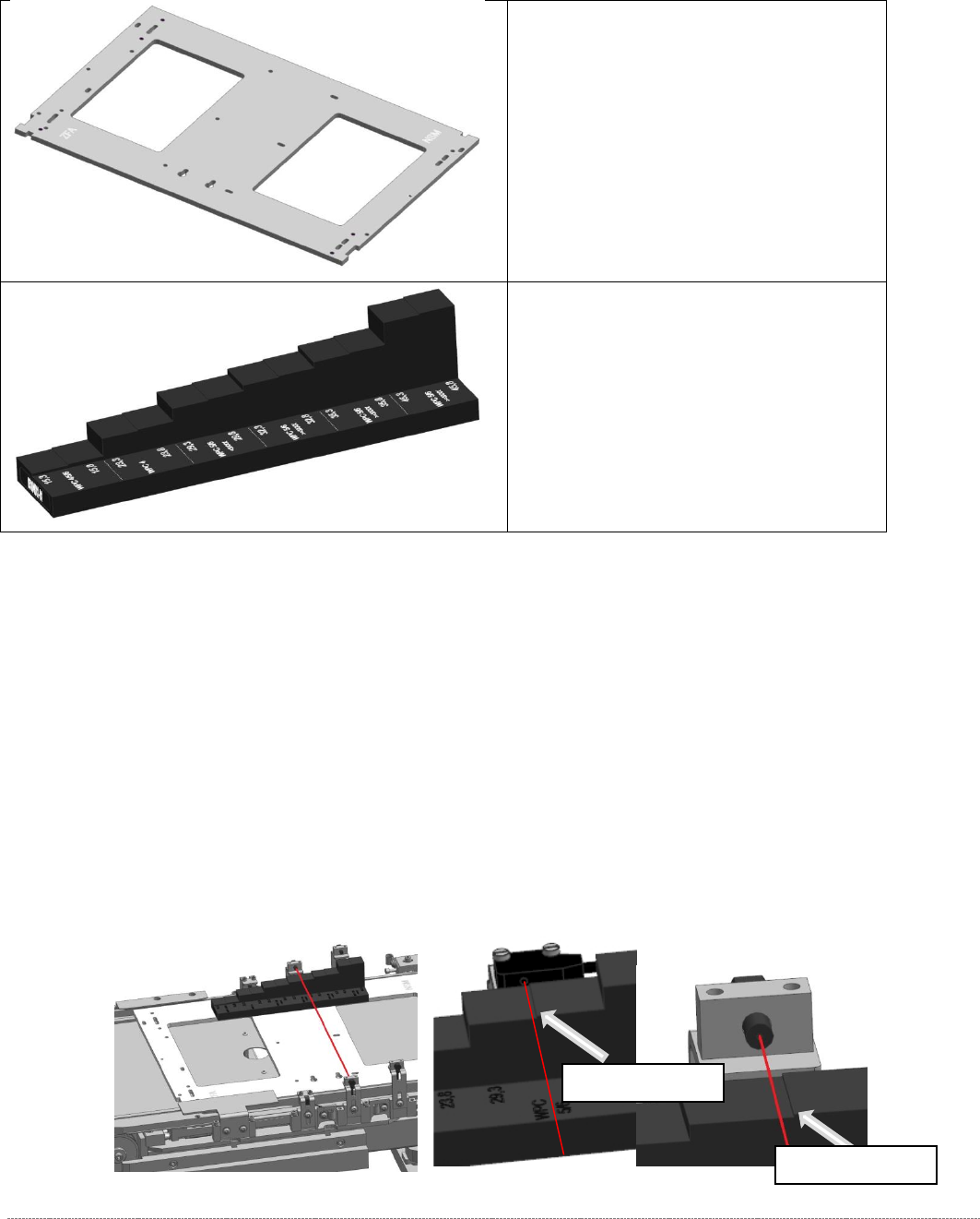
➢ Move the „Jig for WPC4-6 base plate“ [03073064-01] with the corresponding mounting aid to
the position, where the Light barrier has to be made on.
➢ Place the sensor only slightly to the mounting aid and tighten the screw for mounting the
angle at the WPC manually first, so that they can adjust as the adjustments even then.
NOTICE
Labeling
The fibre optic cables are equipped from the factory with a label.
Take this labeling from the old fibre optic cable and put it onto the new one!
The labeling is about:
LA-h and LA-m for the Loading Axis; FA-n, FA-m, FA-h for the Feed Axis.
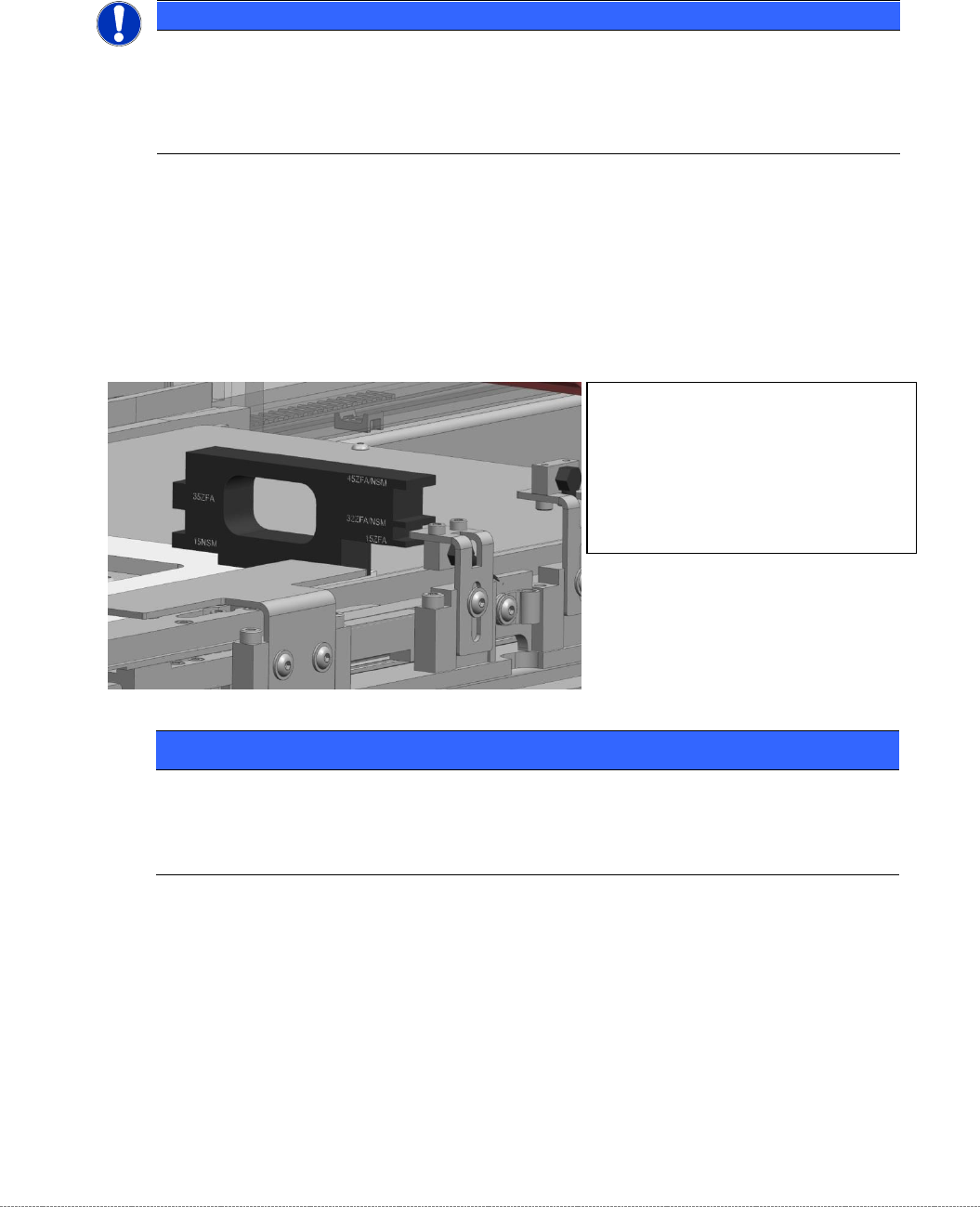
NOTICE
Use of the mounting aids
Place the corresponding light barrier from the top onto the corresponding step of the aid.
Take care, that the mounting aid is laying flat on the base plate.
The ”mounting aid WPC6 HC cpl.”
[03110969-xx] has pins on one side for
positioning on the base plate.
It can be placed thus, in 2 different
orientations on the base plate.
The different heights are labeled directly
beside the corresponding step on the jig

Service Manual Internal WPC5 / WPC6
Page 3-90
Settings
➢ Set the crash light barriers. See "3.7.7
Adjusting the Crash Light Barriers for Component height
"
[➙ 3-91].
NOTICE
Notice the direction of the light beam in the NSM module
In NSM module (at the loading axis) for the standard BE-height (15mm), a light barrier LS TYPE 1 is used.
The recipient of this photocell is on the left side (as seen in the direction to the feed axis).
When mounting the other two BE-heights (32 and 35, or 45mm) from the LS TYPE 2, attention must be paid to
the direction of the light beam. The light output has to be on the left side as well, so that the light beam can not
interfere with the recipient of the BE-height 15mm (LS TYPE 1).
You can simply swap the two fibre optic cables on the control unit if you need to change the light’s direction.
Service Manual Internal WPC5 / WPC6
Page 3-91
3.7.7 Adjusting the Crash Light Barriers for Component height
Tools / Equipment
Measurement setup and procedure
➢ Bring the „Jig for WPC4-6 base plate“ [03073064-02] with the mounted "Adjustment-Jig
crash-LS-WPC4-6 (step)” [03093895-02] in position.
The “step gauge” can be plugged at 3 positions on the base plate.
You start at the position left on the feed axis. This is directly in front of the photocell, so you
can see the position that they should reach well.
➢ Move the base plate with the “step gauge” slowly forward on the feed axis.
The Light barrier must be exactly at the level of the respective stages pair position (e.g.
29mm below).
• „Jig for WPC4-6 base plate“
[03073064-02]
• Adjustment-Jig crash-LS-WPC4-6
(step) [
03093895-02]
Switching stage
Switching stage