00197471-03_Service Manual Internal WPC5_6, EN_01-2019.pdf - 第19页
Service Manual In ternal WPC5 / WPC6 Page 3- 19 3.4 Drive Unit – Feed Axis 3.4.1 Preparations Tools Required • W ater pump pliers • Standard tool with set of Allen wrenc hes • Setting gauge, sm all [03052363- 02] • Bel…

Service Manual Internal WPC5 / WPC6
Page 3-18
CAUTION
Do not move the motor against the brake
Do not move the lifting axis motor shaft against the brake. This could impair the braking function or
damage the brake.
➢ Loosen the two motor support fastening screws (2) sealed with locking varnish.
➢ Loosen (do not remove) the tensioning screw (5) on the tensioning device. This relaxes the
drive toothed belt.
➢ Loosen and remove the 2 fastening screws (2) and then remove the toothed belt (3).
➢ Loosely fix the motor support and drive motor into the installation position, with the 2
fastening screws (2).
➢ Run the new drive toothed belt around the two toothed wheels and tension (pretension) the
toothed belt at the slot provided, with the help of the motor support.
➢ Set the final belt tension. To do this, tension the drive toothed belt at the tensioning device,
with the help of the tensioning screw (5). This moves the motor support accordingly in the
slots.
⇨
Setting value: Set the belt tension to 235 Hz +/- 10 Hz.
➢ Tighten the 2 fastening screws (2) on the motor support, check the belt tension and adjust
where necessary.
➢ Seal the 2 fastening screws (2) with locking varnish.
➢ Calibrate the lifting axis.
NOTICE
Tower moves down
The tower moves down about 1 mm, to the bottom, red bumper.
Service Manual Internal WPC5 / WPC6
Page 3-19
3.4 Drive Unit – Feed Axis
3.4.1 Preparations
Tools Required
• Water pump pliers
• Standard tool with set of Allen wrenches
• Setting gauge, small [03052363-02]
• Belt tension measuring device [00326015-01] with instruction guide
Prerequisite
• Move the tower into the refill position.
• Remove all waffle pack tray carriers (WPTCs) from the tower.
• Move the tower downwards.
⇨
Check sensors and functions ⇨ Check sensors and functions of specific components ⇨ Location ⇨
⇨ Check functions for WPC ⇨ Move into transport position
• Switch the WPC off at the main switch.
• Unplug from the power supply and secure the WPC to prevent unauthorized reactivation.
• Undock the WPC from the SIPLACE machine and move it to a suitable position for service
work.
• Remove the jumper cover.
• Remove the feed axis cover.
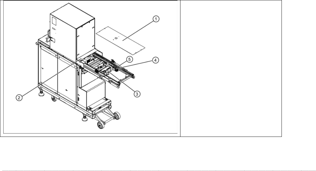
Overview
(1) Feed axis cover
(2) Bridge cover (hand guard on
tower)
(3) Feed axis drive motor
(4) Toothed belt for the drive
(5) Feed axis toothed belt
Service Manual Internal WPC5 / WPC6
Page 3-20
3.4.2 Replace the Feed Axis Drive Motor
Spare Part:
When replacing the drive motors of the WPC5 and WPC 6, it is, with immediate effect,
necessary to take note of the version / item number of the motor, as the successors are not
100% compatible.
Because it is not permitted to install a mixture of new motors in a WPC, the old drives continue
to be available as replacements!
As a result of this incompatibility, the version of the entire WPC was changed when the new
drives were introduced.
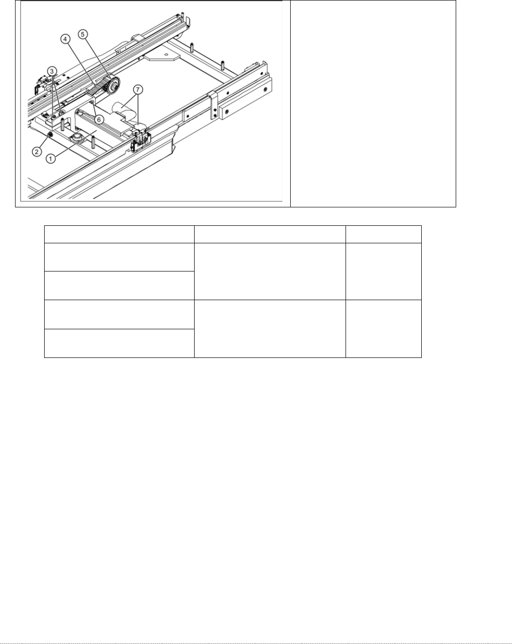
Overview
(1) Feed axis motor, compl.
(2) Tensioning screw
(3) 2 x motor support fastening
screws
(4) Toothed belt for the drive
(5) Deflection pulley
(6) 4 x drive motor fastening screws
(7) Electrical connections
WPC – Type / Version
Spare Part – Name
Part No.
„WPC5 900-950mm / Standard“
[03067619-03]
"Servo motor 1FK7022-5AK71-
1AH3-Z S52"
[03052813-xx]
„WPC6 900-950mm“
[03067618-03]
„WPC5 900-950mm / Standard“
[03067619-04]
“Servo motor 1FK7022-5AK74-
1AH3-Z + S52”
[03161141-xx]
„WPC6 900-950mm“
[03067618-04]