00197471-03_Service Manual Internal WPC5_6, EN_01-2019.pdf - 第98页
Service Manual In ternal WPC5 / WPC6 Page 3- 98 Settings ➢ Check the function and correct position of the li mit switch. The limit switch m ust switch when the lifting axis mov es over the switch (3) (end position). ➢ …
Service Manual Internal WPC5 / WPC6
Page 3-97
3.7.10 Sensor 5 Bottom lifting axis limit switch
Spare Part
• Bottom lifting axis limit switch [03047280-01]
Removal / Installation
➢ Move the lifting axis upwards into the refill position. The limit switch is located in the frame,
under the lifting axis.
➢ Remove the front cover (on the lifting axis drive motor). You can now access the opening for
the limit switch connection cable.
➢ Mark the exact position of the limit switch.
➢ Loosen the two fastening screws (1) on the limit switch.
➢ Remove the fixture plate (4).
➢ Loosen the cable clamps and remove the cable ties.
➢ Unthread the connection cable as far as the control unit back plane and unplug it from the
terminal strip.
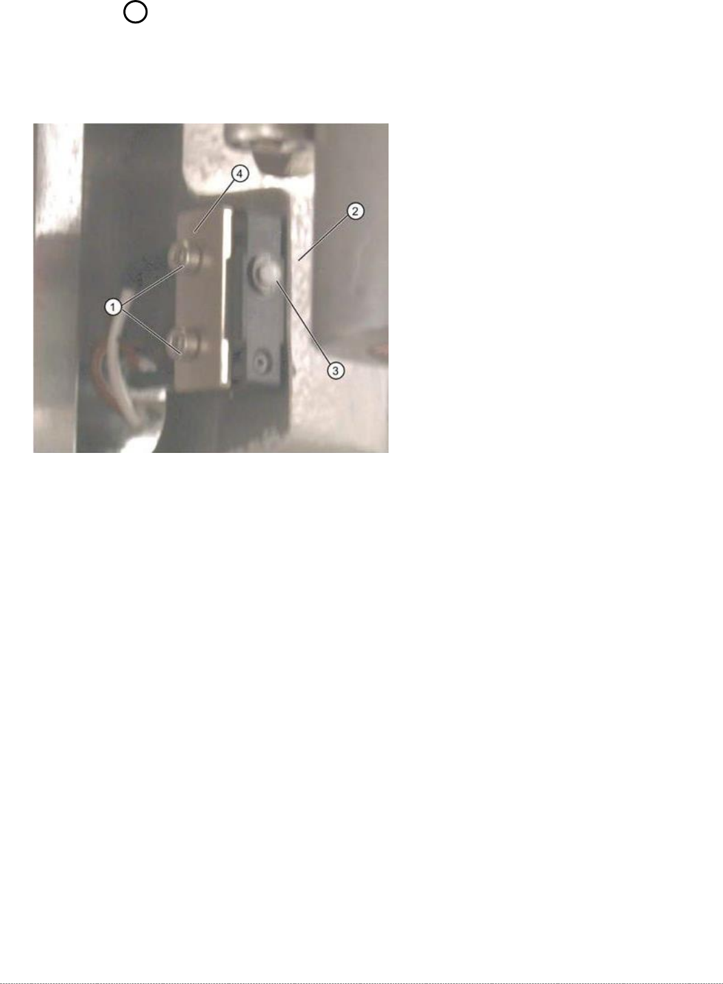
➢ Fit the new limit switch with fixture plate (4) at the marked installation position.
➢ Align the limit switch parallel to the stopper edge (2).
➢ Restore the electrical connection and fix the connection cable into place.

Service Manual Internal WPC5 / WPC6
Page 3-98
Settings
➢ Check the function and correct position of the limit switch. The limit switch must switch when
the lifting axis moves over the switch (3) (end position).
➢ To do this, open the following function in the main view:
⇨ Sensors and Functions ⇨ Location ⇨ Check functions for WPC ⇨ Advanced functions
.
➢ Select the
Feed axis
button in the Axis input area.
➢ Select the
Limit switch
+ button in the input area (see also "4.1.4 Calibrating the Limit Switch"
[➙ 4-122]).
⇨
The lifting axis will be moved so that an actuator on the lifting axis moves over the limit
switch.
The limit (end position) will be calculated.
⇨
Go to the main view and open the menu function
⇨ Sensors and Functions ⇨ Location ⇨ Check functions for WPC ⇨ Advanced functions ⇨ WPC E/A
Ports
.
Make sure that the
Lifting axis bottom limit switch
view option is enabled.
⇨
A dialog box will open and the calculated value will be shown. The permissible limits
(minimum/maximum position) will also be shown. The end position must be within these
limits.
➢ Check the permissible limits against the value actually measured.
➢ If necessary, correct the mechanical position of the limit switch and repeat the
measurement procedure.
➢ If the value is within the permissible limits, save the data by clicking on
Accept
.
➢
Seal the two mounting bracket fastening screws with locking varnish.
Service Manual Internal WPC5 / WPC6
Page 3-99
3.7.11 13 Safety Switch
Spare Part
• Safety switch, closed (safety switch with cable) [03062919-xx]
Removal / Installation
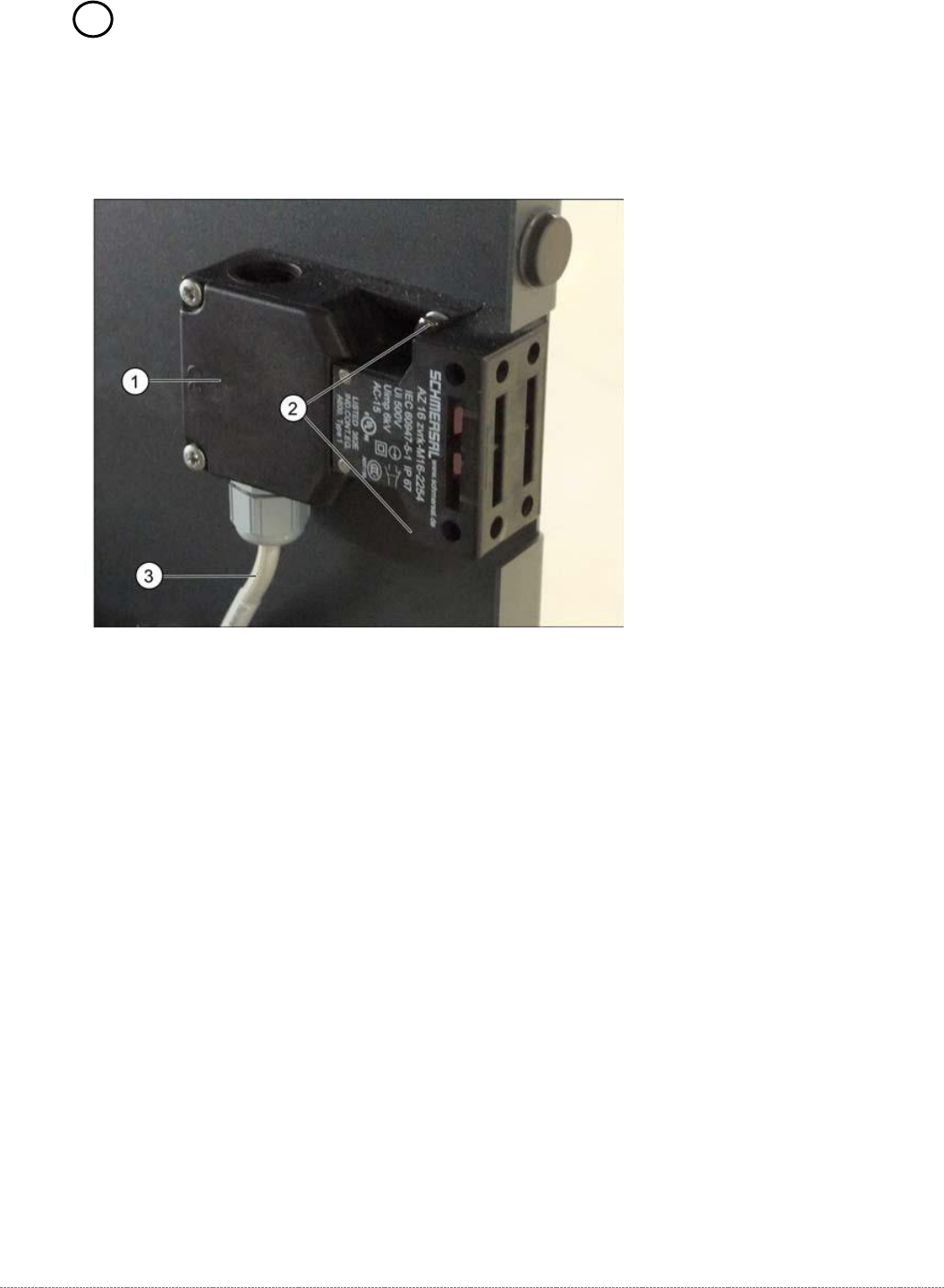
➢ Mark the installation position of the safety switch (1) at the two fastening screws (2) with
slots.
➢ Loosen the two fastening screws (2) and remove the safety switch (1).
➢ Unthread the connection cable (3) as far as the control unit back plane..
The connection cable has two separate connections:
• Unplug the connection cable at terminal strip x12a on the control unit back plane.
• Unplug the connection cable from the safety loop.
➢ Fit the new safety switch at the marked installation position.
➢ Restore the electrical connection and fix the connection cable into place.
Settings
➢ Make sure that the door contact engages properly. If necessary, correct the installation
position at the slots.
➢ Check that the safety switch switches reliably at the docked WPC.