00197471-03_Service Manual Internal WPC5_6, EN_01-2019.pdf - 第41页
Service Manual In ternal WPC5 / WPC6 Page 3- 41 Removal / Install ati on Legend 1. Conn ector X7 (safety sens or for hand guard) 2. Conn ector X2 (lifting magn et for opening the safe ty flap) 3. Fas tening screw on ma…
Service Manual Internal WPC5 / WPC6
Page 3-40
➢ Fit the tensioning device with deflection pulley and fix into place with the two fastening
screws.
➢ Readjust the belt tension (see "3.5.6 Setting the Load Axis Belt Tension" [➙ 3-44]).
➢ Continue with chapter "4.3 Calibrating the Load Axis (WPC6 only)" [➙ 4-135].
See also...
@
3.5.1
Preparations [➙ 3-32]
@
3.5.1.3
Remove the feed axis hand guard [
➙
3-34]
3.5.4 Replace the Lifting Magnets
Spare Parts
• Lifting magnet for opening safety flap 03057345-xx
• Lifting magnet for closing the safety flap 03057344-xx
• 2 x DIN 471-4x0.4-C67 00095480-xx (retaining ring)
• Cable: lifting magnet for closing the safety flap [03058203-xx]
Preparation
➢
Remove the cover of the NSM module (see "3.5.1.1 Remove the Cover on the Load Unit"
[➙ 3-33]).
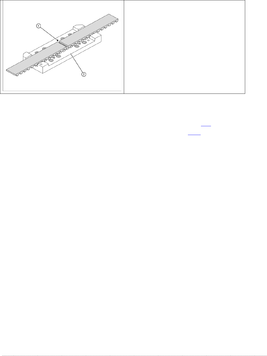
➢ The two ends of the toothed belt must be inserted
into the clamping unit (2) so that the clamping unit
teeth engage with the belt teeth. The two ends must
meet (1).
➢ Note the length of the new toothed belt. The toothed
belt is 1640 mm long/ number of teeth: 328.
➢ If the belt is too long, shorten it to the correct length.
➢ Fit the driver unit onto the clamping unit (2). Tighten
the 4 fastening screws "crosswise" with a torque of
1.3 Nm.
Service Manual Internal WPC5 / WPC6
Page 3-41
Removal / Installation
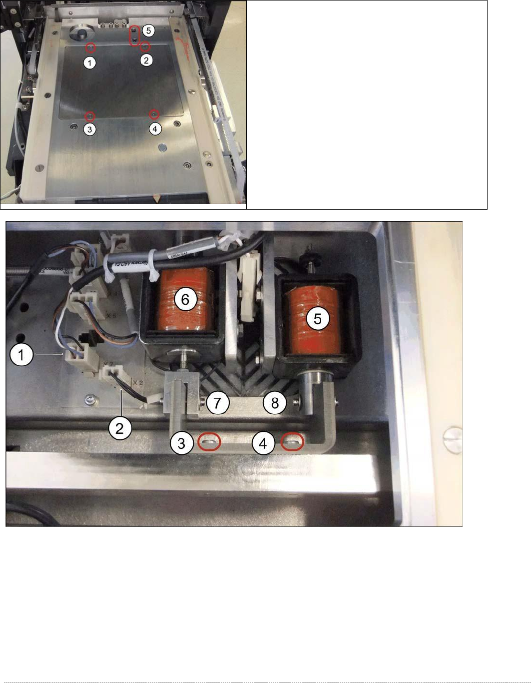
Legend
1. Connector X7 (safety sensor for hand guard)
2. Connector X2 (lifting magnet for opening the safety flap)
3. Fastening screw on magnet holder
4. Fastening screw on magnet holder
5. Lifting magnet 1 assembly / NSM [03053615-xx]
6. Lifting magnet 2 assembly / NSM [03057082-xx]
➢ Loosen the screws marked at 1 to 4 and lift off the
cover. You can now access the lifting magnets.
➢ Loosen the two screws at 5.

Service Manual Internal WPC5 / WPC6
Page 3-42
➢ Unplug the connector X2 (2) belonging to the cable for the lifting magnet which closes the
safety flap and connector X7 (1) from the circuit board.
➢ Loosen the screws fastening the magnet holder (3 and 4) and lift out the holder with the
magnets.
➢ Dismantle the magnets to be replaced from the holder. To do this, loosen the relevant circlip
(at 7 for lifting magnet 1 or 8 for lifting magnet 2) and pull out the axis bolt. Check whether
there are any washers fitted and make a note of their positions if there are any..
Installation
➢ Set the same lift as used for the dismantled magnets.
➢ Insert the new lifting magnets with the axis bolts into the mount.
➢ Fix the axis bolt into place with the washers and the circlip.
➢ Fit the new lifting magnet by following the instructions for removal in reverse order.
NOTICE
Circlip
The circlip can be easily damaged. Take great care when removing it.