00197471-03_Service Manual Internal WPC5_6, EN_01-2019.pdf - 第82页
Service Manual In ternal WPC5 / WPC6 Page 3- 82 3.7.6 Crash Light Barriers for Component Height 2 3 10 11 19 20 With the introduction of WPC5/WPC6 Vers ion -03, new types for Crash-L ight barrier compo nent heights are…
Service Manual Internal WPC5 / WPC6
Page 3-81
Installation
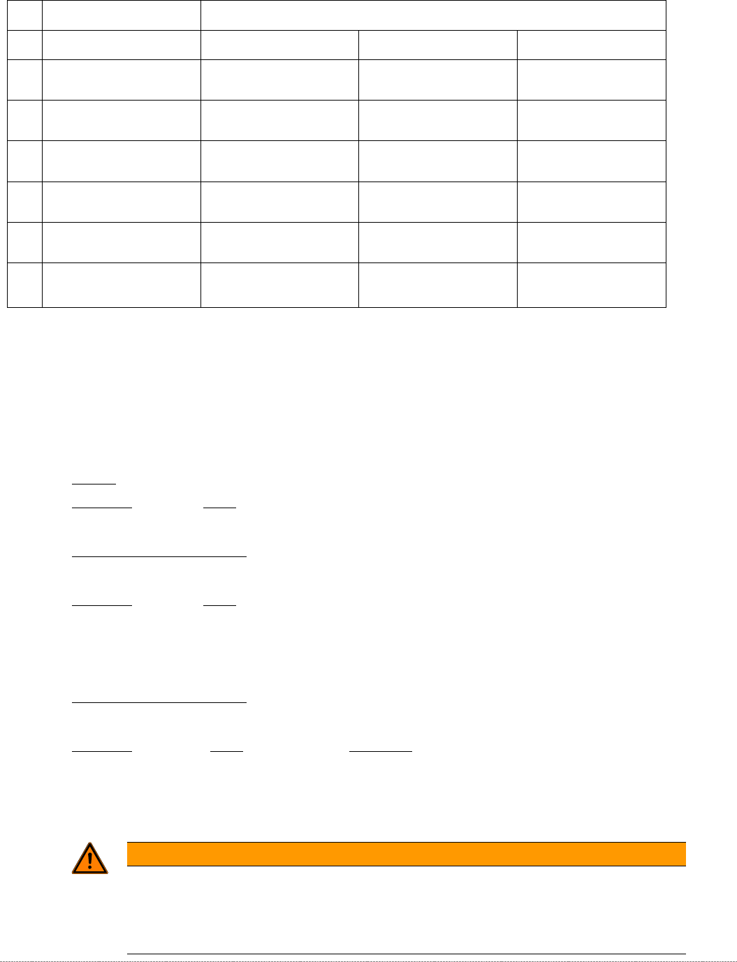
➢ Align the reference sensor and screw to its installation point.
➢ Note the installation position. The sensor surface must point downwards and the LED
upwards.
➢ Run the connection cable.
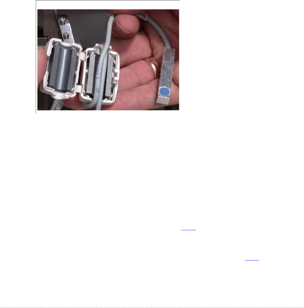
➢ Leave a sufficiently large loop of cable, so that you can fit the cable in the ferrite core.
➢
Restore the electrical connection and fix the connection cable into place.
➢ Insert the connection cable into the ferrite core (one loop).
➢ Press the two halves together so that the fixture engages.
Settings
➢ Check the function and correct position of the reference sensor. The sensor must trigger
when the driver actuator is just below the sensor. (Reference point).
➢ To do this, open the station software menu
⇨ Sensors and Functions ⇨ Location ⇨ Check functions for WPC ⇨ Advanced functions.
➢ Enable the feed axis and click on the Reference bero button.
The feed axis will be moved so that the driver actuator triggers the reference sensor. The
reference point will be calculated.
The calculated value will be shown and can then be saved with the
Commit
button.
➢ If an error message appears, correct the mechanical position by adjusting the cam on the
driver (see "4.2.3 Reference Proximity Switch (Bero)” [➙ 4-129]) and repeat the measuring
process.
➢ Coat the cam fastening screw with locking varnish.
➢ Calibrate the reference sensor (see "4.2.3 Reference Proximity Switch (Bero)" [➙ 4-129).
Service Manual Internal WPC5 / WPC6
Page 3-82
3.7.6 Crash Light Barriers for Component Height 2 3 10 11 19 20
With the introduction of WPC5/WPC6 Version -03, new types for Crash-Light barrier component
heights are introduced.
All WPC5 and WPC6 < Serial-No.: 3xxx- exhibit LB-type 1.
All WPC5 and WPC6 > Serial-No.: 3xxx- exhibit LB-type 2 and LB-type 1.
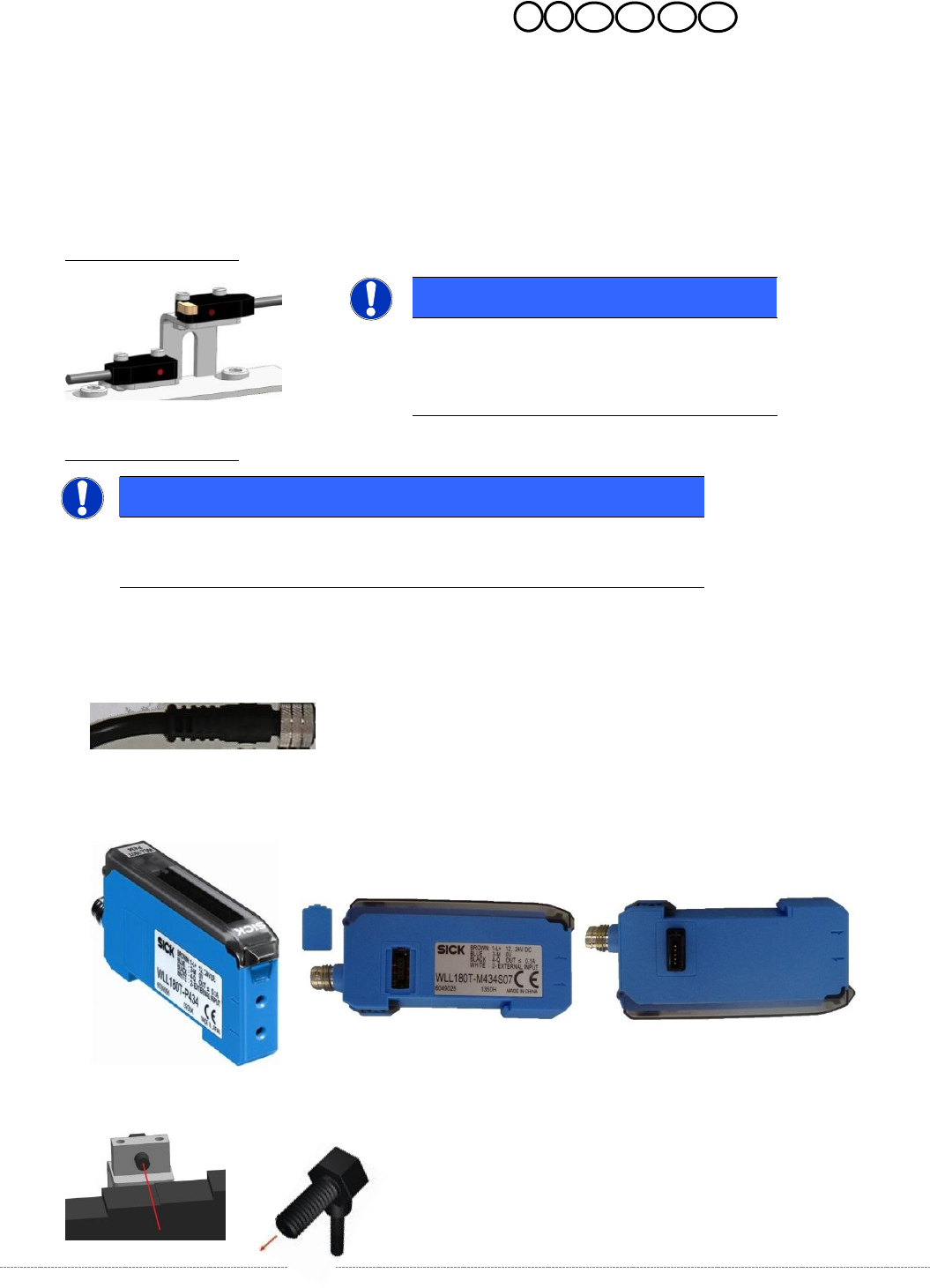
Description LB-type 1:
Description LB-type 2:
For this LB-type we have 3 spares.
1. Cable for Crash-LB CO-height,
2. Control unit LB (there are each WLL180T-M and WLL180T-F); the units are connected to each
other via a connector on the side of the unit.
3. optical fibre.
NOTICE
Spare Parts
Part numbers, see table spare parts and the
following overview.
NOTICE
Spare Parts
Part numbers, see table spare parts and the following overview.
Service Manual Internal WPC5 / WPC6
Page 3-83
Spares
Overview
For the individual WPC types, different CO-Heights to be adjusted.
WPC4: a distinction is the setting for Standard- and High- Components.
Standard: 15mm; High: 23mm.
WPC5/6 < Serial-No. 3xxx:
a distinction is the setting for Standard- and High- Components.
Standard: 15mm; High: 29mm.
Option: On WPC5 from Serial No. B1485 it is possible, in context with a „Very High Force
Pick&Place Modul (VHF-30mm/70N), to set 35mm for high components.
WPC5/6 > Serial-No. 3xxx:
a distinction is the setting for Standard-, High- and Very high- components.
Standard: 15mm; High: 32mm; Very high: 35mm (45mm Optional)
Option: In context with a „Very High Force TWIN-Head (VHF-40mm/70N), the Position Very
high components is set to 45mm.
WARNING
! DANGER of CRASH !
The Setting of 45mm requires a higher position of the gantry!.
Therefore, the 45mm can only be used with the „Twin VHF Package, 40mm, 70N with
Gantry“ (Sales number 00519986-xx)!
No.:
LS Type 1:
LS type 2:
Cable for Crash-LB CO Height
Control units
Fibre optic cable
2a/
2b
„Crash light barrier normal
components“
[03057282-xx]
„Crash-LS feed-axis normal
components”
[03108652-xx]
„Fibre opt.sensor WLL180T-M
preconfig SXa“
[03093294-xx]
„Fibre optic cable LL3-TV05
2m“
[03092407-xx]
3a/
3b
„Crash light barrier high
components“
[03057283-xx]
„Crash-LS feed-axis middle
compononents“
[03108654-xx]
„Fibre opt.sensor WLL180T-F
preconfig SXa“
[03093295-xx]
„Fibre optic cable LL3-TV05
2m“
[03092407-xx]
19a/
19b
„Crash-LS load-axis high
components“
[03108656-xx]
„Fibre opt.sensor WLL180T-F
preconfig SXa“
[03093295-xx]
„Fibre optic cable LL3-TV05
2m“
[03092407-xx]
10a/
10b
„Crash-LS normal components
BA“
[03057012--xx]
11a/
11b
„Crash-LS high components BA”
[03057291--xx]
„Crash-LS load-axis middel
components“
[03108658-xx]
„Fibre opt.sensor WLL180T-M
preconfig SXa“
[03093294-xx]
„Fibre optic cable LL3-TV05
2m“
[03092407-xx]
20a/
20b
„Crash-LS Beladeachse hohe
Bauteile WPC6“
[03108659-xx]
„Lichtleiter-Sensor WLL180T-F
vorprog SXa“
[03093295-xx]
„Fibre optic cable LL3-TV05
2m“
[03092407-xx]]
Table 1: Spares Overview Ligth barrier for component height.