00197471-03_Service Manual Internal WPC5_6, EN_01-2019.pdf - 第159页
Service Manual In ternal WPC5 / WPC6 Page 5-159 5.5.4 Setting the top, front guide rails (position of the to we r cov er) Figure 5. 17 : Fron t, top guide rails Move the tower up wards, until th e gauge is above the gu…
Service Manual Internal WPC5 / WPC6
Page 5-158
5.5.3 Bottom guide rails, bottom position
Now move the tower further down until it is just above the bottom lifting axis buffer
Figure 5.16: Setting the position of the bottom rear guide rails, 0.5 mm..
Again use a feeler gauge to set a gap of 0.5 mm between the guide rail and the baseplate of the
gauge.
Now move the tower back up until the gauge is at the same height as the alignment marks for the
start of the chamfer of the bottom guide rails.
Used a feeler gauge to check that the gap between the guide rail and the baseplate of the gauge is
still 0.2 mm and adjust it if necessary.
If you need to adjust the positions of the bottom guide rails, you must remove the side covers of the
WPC. Refer to Figures 10 and 13 in this document.
NOTICE
Using 2 base plates
If you are working with two gauges, you can now move the tower approximately 10 cm
upwards to insert the 2nd gauge in Level 24 (the 5th level from the top).
Clamp the second gauge in the same way as you did the first with the „Gauge base
setting base plate position“ [03110862-xx] touching the lifting axis guide rails.
Service Manual Internal WPC5 / WPC6
Page 5-159
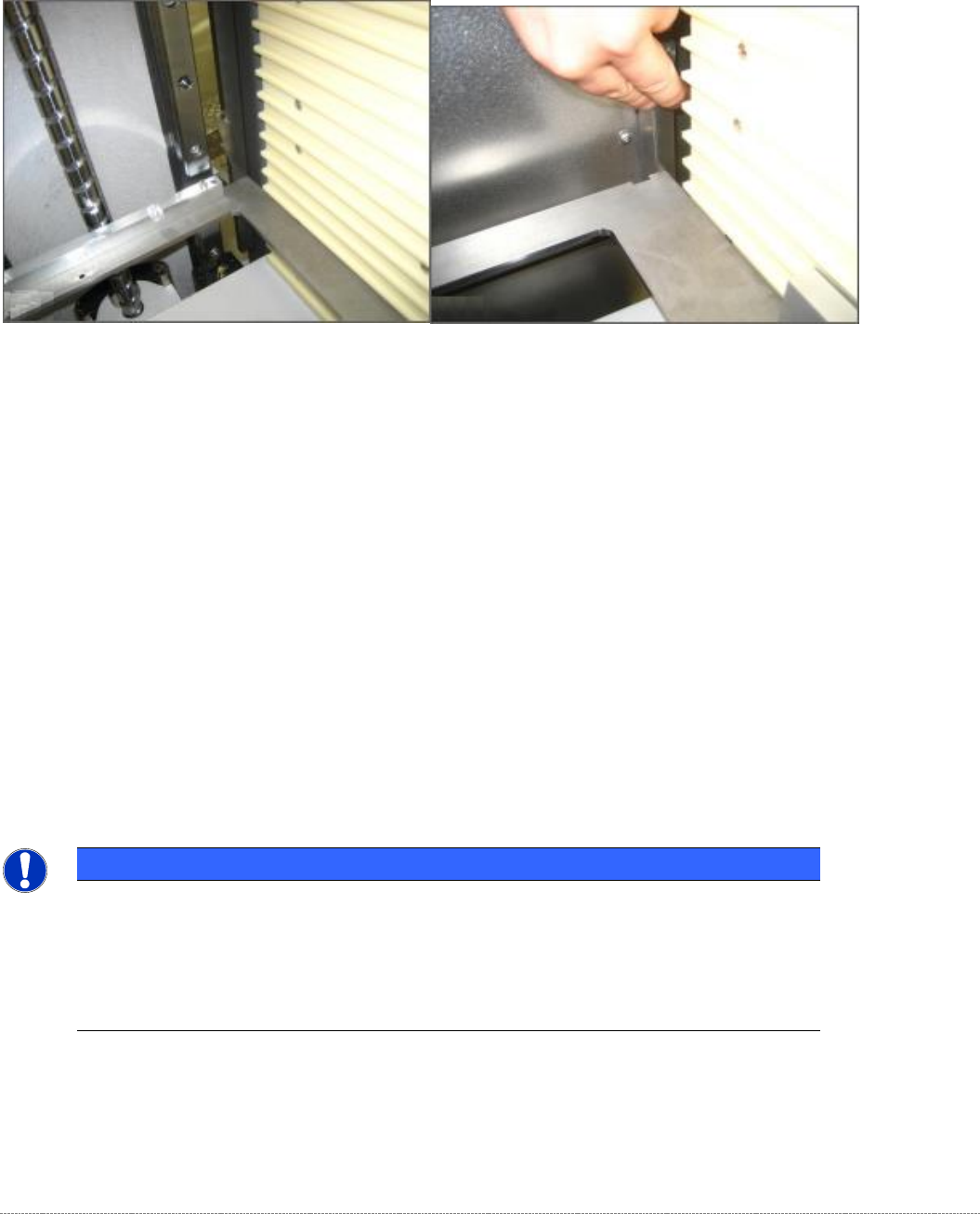
5.5.4 Setting the top, front guide rails (position of the tower cover)
Figure 5.17: Front, top guide rails
Move the tower upwards, until the gauge is above the guidelines on the starting slopes of the upper
guide rails.
These guide rails are mount on the front part of the tower cover. Therefore, this is a setting,
depending on the adjustment of the tower cover position itself.
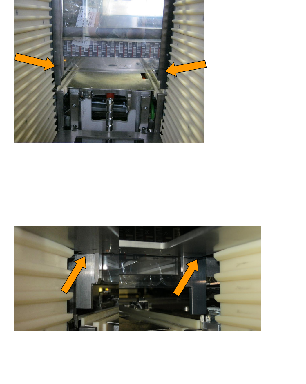
Figure 5.18: Gap at the front, top guide rail, checking the bottom position, 0.2 mm
First check the gap between the gauge and the guide rails using a 0.2 mm feeler gauge.
Service Manual Internal WPC5 / WPC6
Page 5-160
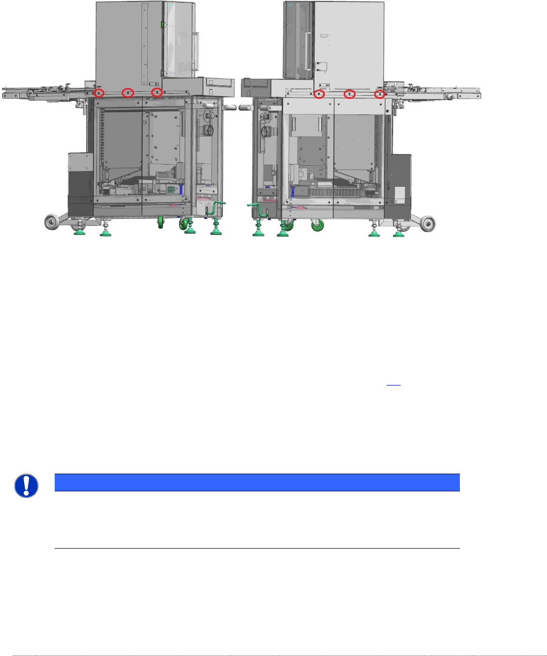
If the position needs to be corrected, the tower cover must be moved.
To do this, you should release (but not remove) all six screws that secure the tower cover to the
frame of the WPC.
Figure 5.19: Screws securing the tower cover to the WPC frame
Now move the top cover (tower cover) to achieve a gap of 0.2 mm between the two front guide rails
and the gauge.
Now remove the gauge from Division 5 and insert it in division 24 (fifth from the top).
Clamp the gauge in the same way as you did in Division 5 , with the „Gauge base setting base plate
position“ [03110862-xx] touching the guide rails of the lifting axis. See section 5.3.
Move the tower up.
Use a feeler gauge to check the gap between the front guide rails and the baseplate of the gauge.
It should be in the range 0.2 mm to 0.7 mm.
NOTICE
Using 2 base plates
If you are using two gauges, you can now set the bottom and top positions at the top,
front guide rail together.
Finally tighten the 6 securing screws for the cover again. To do this, use a torque wrench set to a
tightening torque of 5 Nm.
Then apply red screw locking varnish [00318197-01] to these screws.