00197471-03_Service Manual Internal WPC5_6, EN_01-2019.pdf - 第86页
Service Manual In ternal WPC5 / WPC6 Page 3- 86 Tools / Equipment Example: „ Jig for WPC4-6 ba se plate “ [0307306 4-02] with „ mounting aid WPC 4-6 old LB “ [031 10476-xx]; the aid can be used on 4 different po sition…
Service Manual Internal WPC5 / WPC6
Page 3-85
At WPC4 and at WPC5 / WPC6 up to serial no. 3xxx-, light barriers with normal electrical conection are in
use, which were directly connected to the WPC control unit (called LB type 1 in the following).
At WPC5 / WPC6 from serial no. 3xxx-, new light barierer are in use, which are using a fibre optic cable.
Those are connected to a control unit, which is finaly connected to the WPC control unit (called LB type 2 in
the following).
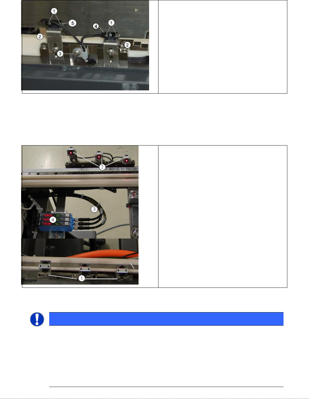
Overview
LB Type 1
1. Fixing screw for Crash light barrier.
2. Fixing angle Crash light barrier (transmitter)
3. Cable fixing Crash light barrier.
4. Crash light barrier normal height Components, with
LED
5. Crash light barrier high components, with
LED.
Overview LB Type 2
1. Fibre optic cables on holders (here Receiver).
2. Fibre optic cables on holders (here
Transmitter).
3. Cable for Crash light barrier CO heights.
4. Control units:
„Fibre opt.sensor WLL180T-M preconfig SXa“
[03093294-01]
„Fibre opt.sensor WLL180T-F preconfig SXa“
[03093295-01]
Data sheet see attachment of this document!
NOTICE
Spare Parts
At LB Type 1, transmitter and receiver are one spare part.
The transmitter and the receiver of one light barrier (different cable length depending on
height type) are delivered as one spare with one part number.
Depending on the error occurring, you may need to replace the transmitter and receiver
together.
Service Manual Internal WPC5 / WPC6
Page 3-86
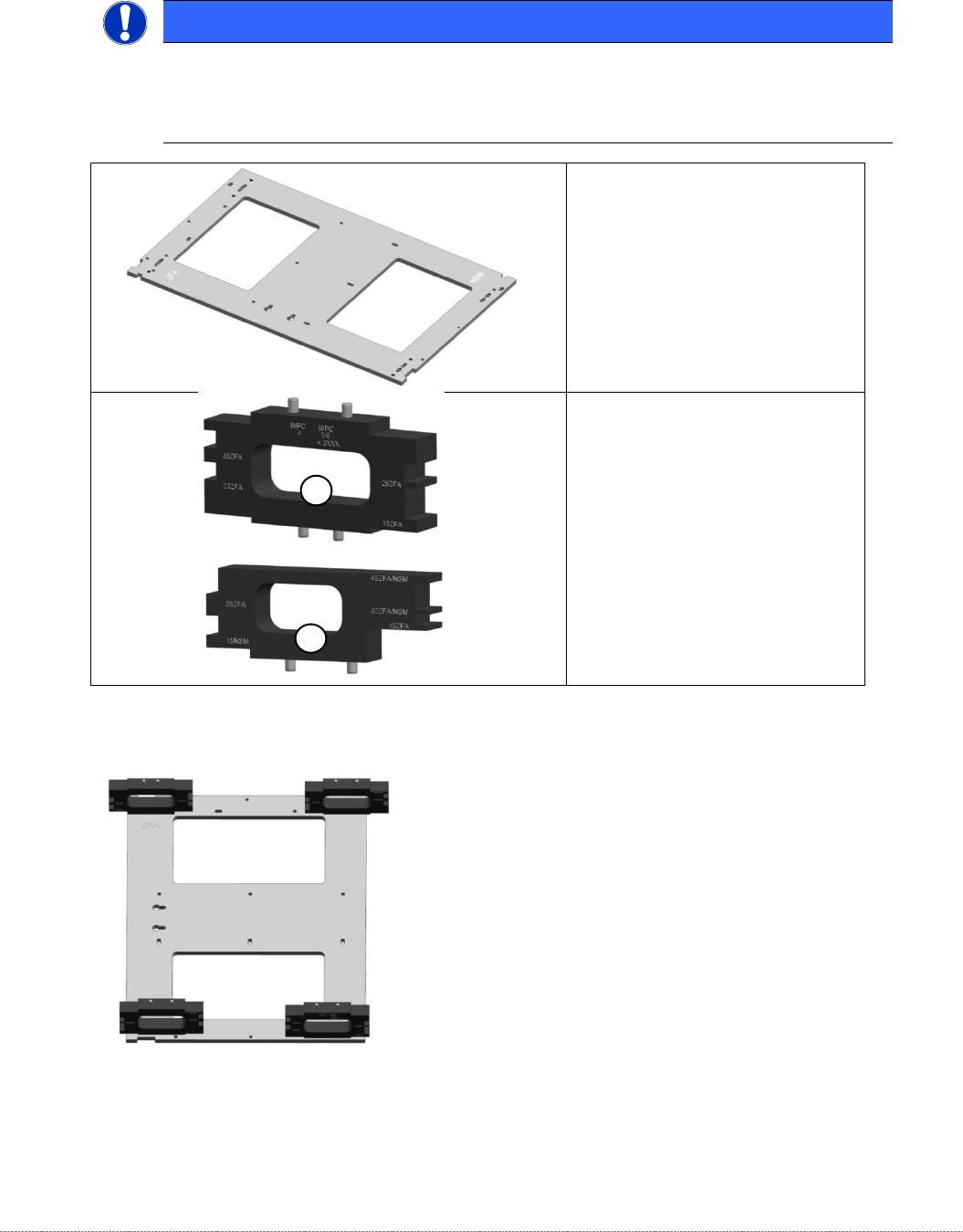
Tools / Equipment
Example:
„
Jig for WPC4-6 base plate
“
[03073064-02] with
„
mounting aid WPC 4-6 old LB
“
[03110476-xx]; the aid can be used
on 4 different positions.
NOTICE
Simplified mounting
To bring the sensor easy into the right position, you can use the „Jig for WPC4-6 base
plate“ [03073064-01], together with the corresponding Mounting aid.
•
„Jig for WPC4-6 base plate“
[ 03073064-02]
1) „Mounting aid WPC4-6 old LB“
[03110476-xx]
for all WPC4, as well as WPC5
and WPC6 up to serial no.
3xxx-
2) “Mounting aid WPC6 HC cpl.“
[03110969-xx]
for all WPC5 and WPC6 from
serial no. 3xxx-
1
2
Service Manual Internal WPC5 / WPC6
Page 3-87
Removal / Installation
LB Type 1
➢ Loosen the two fastening screws (1) for the relevant sensor (transmitter or receiver) on the
mounting bracket (2).
➢ Loosen the screws fastening the cable fixtures (3) and unthread the light barrier cable.
➢ Remove the black plastic guide from the left side of the feed axis, so that the connectors and
cables can be threaded in and out.
➢ The cables are run from the right-hand side, along the underside of the feed axis to the left-
hand side. From there, they are run together with the cables from the left side to the back
plane of the control unit.
➢ Loosen the cable clamps and remove the cable ties.
➢ Unthread the connection cable as far as the control unit back plane and unplug it from the
terminal strip.
➢ Fit the new sensor on the mounting bracket (2).
➢ Align the sensor parallel to the mounting bracket (2).
➢ Restore the electrical connection and fix the connection cable into place.
➢ Move the „Jig for WPC4-6 base plate“ [03073064-01] with the corresponding mounting aid to
the position, where the Light barrier has to be made on.
➢ Place the photocell only slightly to the mounting aid and tighten the screw for mounting the
angle at the WPC manually first, so that they can adjust as the adjustments even then.
Settings
➢ Set the crash light barriers. See "3.7.7
Adjusting the Crash Light Barriers for Component height
"
[➙ 3-91].
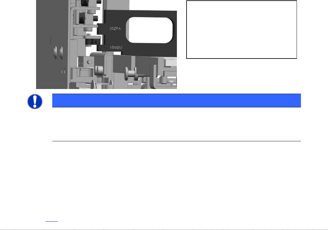
NOTICE
Use of the mounting aids
Place the corresponding light barrier from the top onto the corresponding step of the aid.
Take care, that the mounting aid is laying flat on the base plate.
The „Mounting aid WPC 4-6 old LB“
[03110476-xx] has pins on 2 sides, to be
positioned on the base plate.
So it can be placed on the base plate in 4
different orientations.
The different heights are labeled directly
beside the corresponding step on the jig