00197471-03_Service Manual Internal WPC5_6, EN_01-2019.pdf - 第148页
Service Manual In ternal WPC5 / WPC6 Page 5-148 5.3 Positioning and securing the gauge NOTICE Removing carrie r plates from the tow er Remove all carrier plates from the tower. Only the gauges are r equired for the set…
Service Manual Internal WPC5 / WPC6
Page 5-147
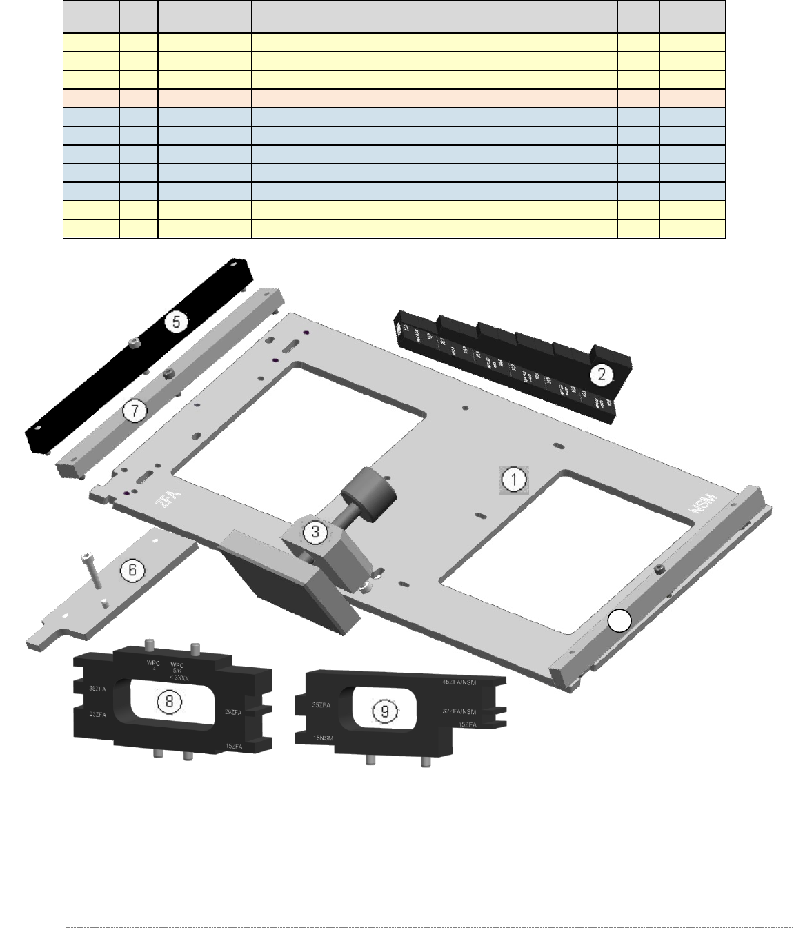
5.2 Construction of the Gauge, parts list
Level ²
Pos.
Part Number
FS
Product Name
For
WPC
Service-
Level ³
0
03093396-
02
Adjustment and testing jig WPC4-6 compl.
4/5/6
T3
1
1
03073064-
02
Jig for WPC4-6 base plate
4/5/6
T1
1
2
03093895-
02
Adjustment-Jig crash-LS-WPC4-6 (step)
4/5/6
T1
1
03093896-
02
service paket jig WPC4-6
4/5/6
T3
.2
3
03093864-
01
clamping readout tower adjust.WPC4-6 cpl
4/5/6
T3
.2
4
03093815-
01
rail for ingate cmpl.
6
T3
.2
5
03093816-
01
Bar for crash-LB transfer pos. feed axis
5/6
T3
.2
6
03093820-
01
Jig stopper spring cmpl.
5/6
T3
.2
7
03110862-
01
Gauge base setting base plate position
4/5/6
T3
1
8
03110969-
01
Mounting aid WPC6 HC cpl.
4/5/6
T1
1
9
03110962-
01
Mounting aid WPC4-6 old LB cpl.
4/5/6
T1
Figure 5.1: „Adjustment and testing jig WPC4-6 compl.“ [03093396-02]
² : Level in Bill of material (BOM). Level . 2 means: this article is part of the upper laevel 1.
³ : Availability in Service: T1 - Tool Level 1 (Customer); T3 - Tool Level 3 (Service SIPLACE)
4
Service Manual Internal WPC5 / WPC6
Page 5-148
5.3 Positioning and securing the gauge
NOTICE
Removing carrier plates from the tower
Remove all carrier plates from the tower. Only the gauges are required for the settings
described below.
• Remove all additional gauges from the baseplate and only use the "Jig for WPC4-6 base
plate" [03073064-01].
NOTICE
Using 2 base plates
In order to facilitate setting the guide rails in particular, it is recommended that you use
2x "Jig for WPC4-6 base plate" [03073064-01] to avoid the need to move a single gauge
from the top to the bottom.
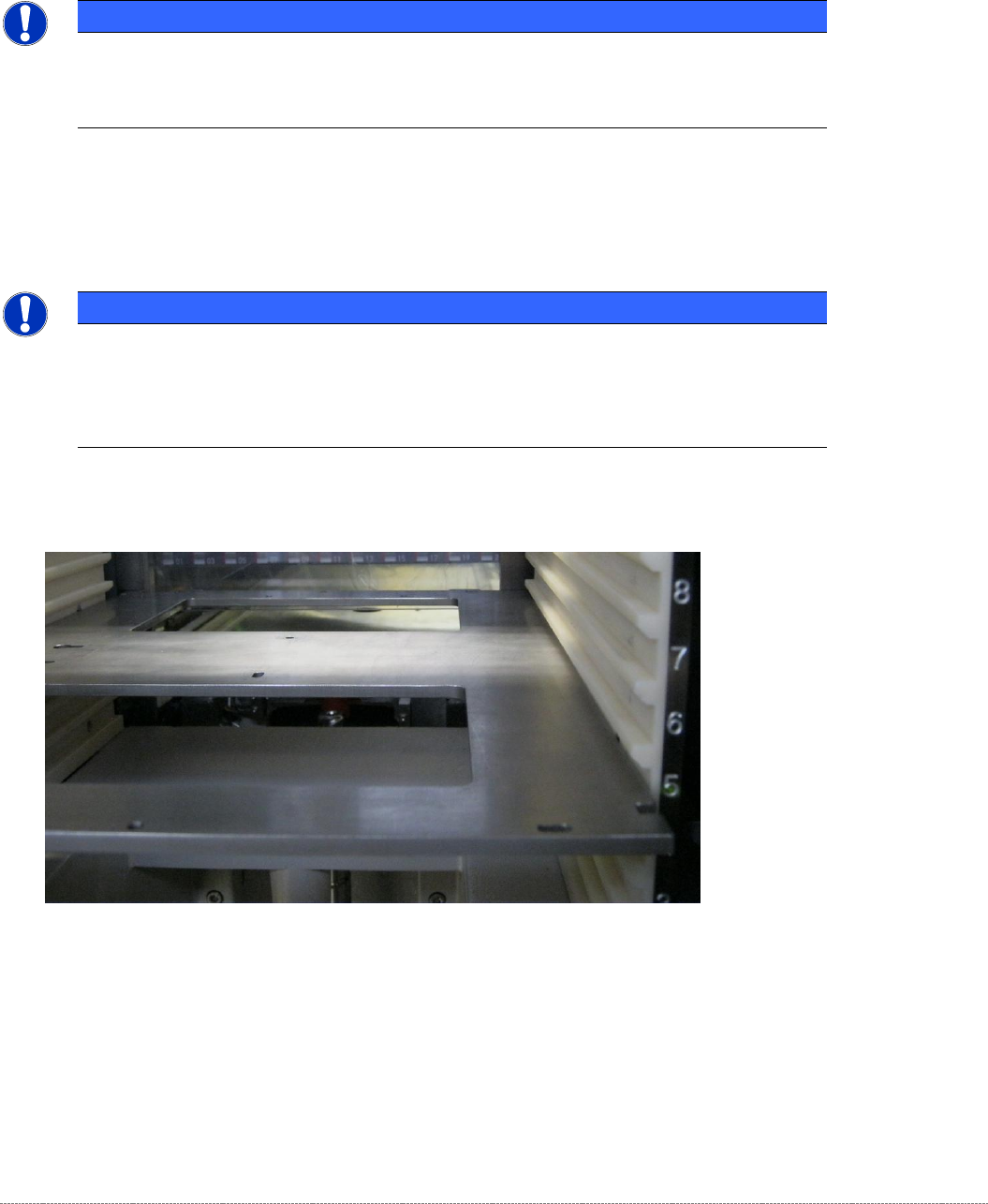
• Position the gauge in Level 5.
Figure 5.1: Positioning the gauge in Level 5.
• Step the tower (lifting axis) downwards until the gauge is at the same height as the linear
guide rails of the lifting axis.
Service Manual Internal WPC5 / WPC6
Page 5-149
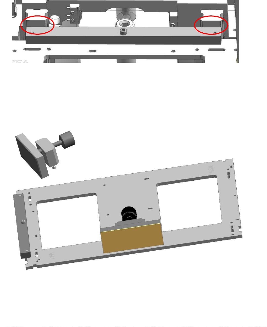
• Plug the „Gauge base setting base plate position“ [03110862-xx] on the base plate.
• Move the gauge into the tower, until the „Gauge base setting base plate position“
[03110862-xx] strikes the guide rails on both sides.
Figure 5.2: Strike the Guide rails of the lifting axis with the “Gauge base setting base plate position” [03110862-01]
• Attach the "clamping readout tower adjust.WPC4-6 cpl." [03093864-01] to the base unit.
The mounting for the clamp on the baseplate is a pair of keyhole slots.
There is no need to tighten the clamp on the baseplate. It is sufficient to tighten the screws
by hand. When the clamp is closed, the attachment is automatically pushed into the end of
the slots.
Figure 5.3: Base plate gauge with clamp attachment.