00197471-03_Service Manual Internal WPC5_6, EN_01-2019.pdf - 第114页
Service Manual In ternal WPC5 / WPC6 Page 4-114 4 Calibrating the Sensors in the Station Soft w are After replac ing the sen sors , you need to cal ibrate the n ew sens ors. This c an t ake se veral minut es. ➢ Befor e…
Service Manual Internal WPC5 / WPC6
Page 3-113
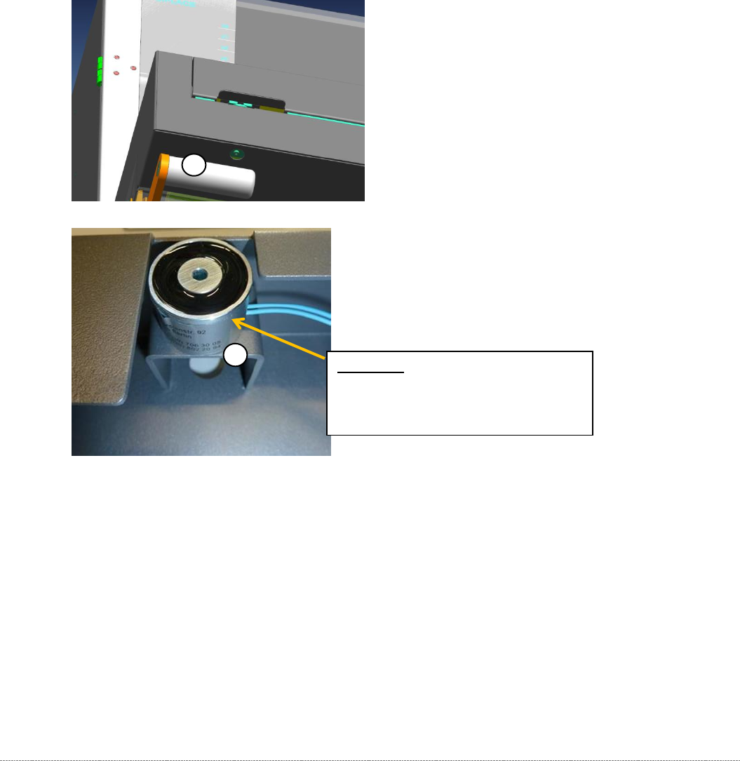
3.7.19 Loading flap close magnet
Spare Parts
• Lading flap close magnet [03083123-xx]
Removal / Installation
The holding magnet is mounted on a pedestal (1) in the NSM panel with 3 "NB602 M4x8"
screws [03005643].
The 3 screws can be accessed from the outside through a hole in the underside of the panel
(2).
The magnet has a 20 cm long cable with a 2 pin plug firmly attached.
The magnet is plugged into connector X30a on the back of the "backplane control
module" via the "cable: holding magnet loading flap" [03083109-01].
The adjustment with respect to the distance of the magnet to the loading door via the
"magnetic plate", which is mounted on the tailgate.
1
2
Attention: Do not clamp the cable!
Lead the cable through the notch on
the magnet.
Service Manual Internal WPC5 / WPC6
Page 4-114
4 Calibrating the Sensors in the Station Software
After replacing the sensors, you need to calibrate the new sensors. This can take several
minutes.
➢ Before calibration, perform a complete reference run of the machine.
➢
Before calibration, remove all waffle-pack tray carriers (WPTCs) from the WPC.
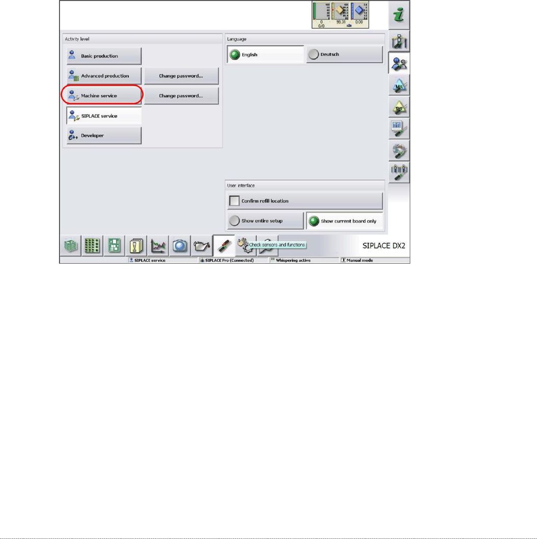
➢
Log in as
Machine Service
.
➢
Select the
Check sensors and functions
button.
Service Manual Internal WPC5 / WPC6
Page 4-115
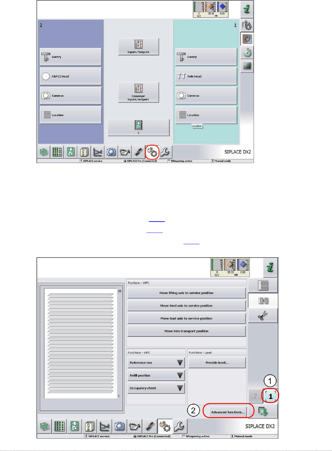
➢ Select the required location (1). (location 1 in this example)
➢ Select the
Advanced functions
button.
The relevant axis can be selected in the following view.
See:
• "4.1 Calibrating the Lifting Axis"
[
➙
4-117]
• "4.2 Calibrating the Feed Axis" [
➙
4-126]
• "4.3 Calibrating the Load Axis (WPC6 only)" [
➙
4-135]