00197471-03_Service Manual Internal WPC5_6, EN_01-2019.pdf - 第64页
Service Manual In ternal WPC5 / WPC6 Page 3- 64 3.6.5 Power Supply Unit 3.6.5.1 Repla cing the P rotect ive Con tactor Combinatio n (SSK ) Spare Part • Protective contactor c ombination ( SSK) 3TK2828- 1BB41 [0037264 9…

Service Manual Internal WPC5 / WPC6
Page 3-63
Non-Stop-Module Elektrics [03057797-xx]
Parts
Quantity
Name
Item no.
1
Table plate electrics
03057798-xx
1
Power cable load axis
03056950-xx
1
Signal cable load axis
03056948-xx
1
Reference point proximity switch load axis
03056947-xx
1
ble: operat. button with signal light
03057602-xx
1
Cable: Safety sensor loading flap
03057600-xx
1
Cable: safety sensor hand guard
03057601-xx
1
Cable: lifting magnet safety flap closing
03057603-xx
1
Cable: lifting magnet safety flap opening
03057604-xx
1
Crash light barrier normal components load
axis
03057012-xx
1
Crash light barrier high components load axis
03057291-xx
1
Cable: sensor safety flap open
03057598-xx
1
Cable: sensor tray correctly inserted
03057599-xx
1
Cable: sensor tray detection load axis
03071453-xx
Service Manual Internal WPC5 / WPC6
Page 3-64
3.6.5 Power Supply Unit
3.6.5.1 Replacing the Protective Contactor Combination (SSK)
Spare Part
• Protective contactor combination (SSK) 3TK2828-
1BB41 [00372649-xx]
Removal / Installation
➢ Label all connections for easier installation later.
➢ Unplug all connections from the protective contactor combination.
➢ Lever the protective contactor combination off the mounting rail.
➢ Connect the new protective contactor combination to the mounting rail and restore the
electrical connections..
Settings
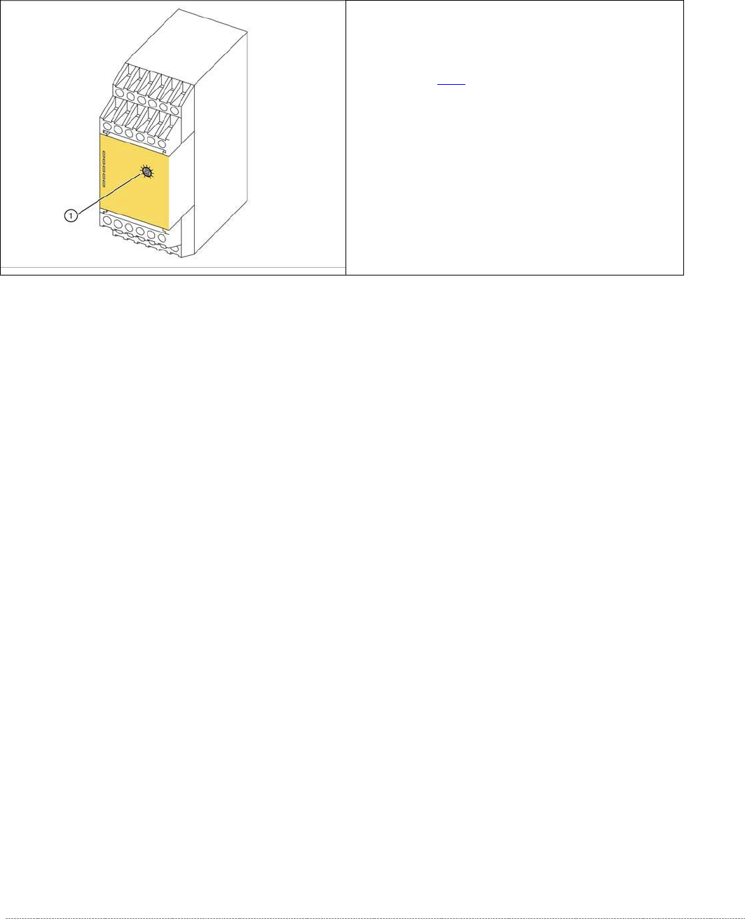
➢ Adjust the setting screw (1) to a value of 0.5 (seconds). If the value is set too high, an error
message will be issued.
➢ Seal the setting screw with locking varnish.
The protective contactor combination (SSK) is
located at the front of the electrical unit (see "3.6.2
Overview"[➙ 3-47]).
1. setting screw
Service Manual Internal WPC5 / WPC6
Page 3-65
3.6.5.2 Replacing the Emergency STOP and Protective Door Monitor (WPC6 only)
Spare Part
• Emergency STOP and guard door monitor [03056745-xx]
Removal / Installation
➢
➢
➢
➢
➢
➢
➢
➢
➢
➢
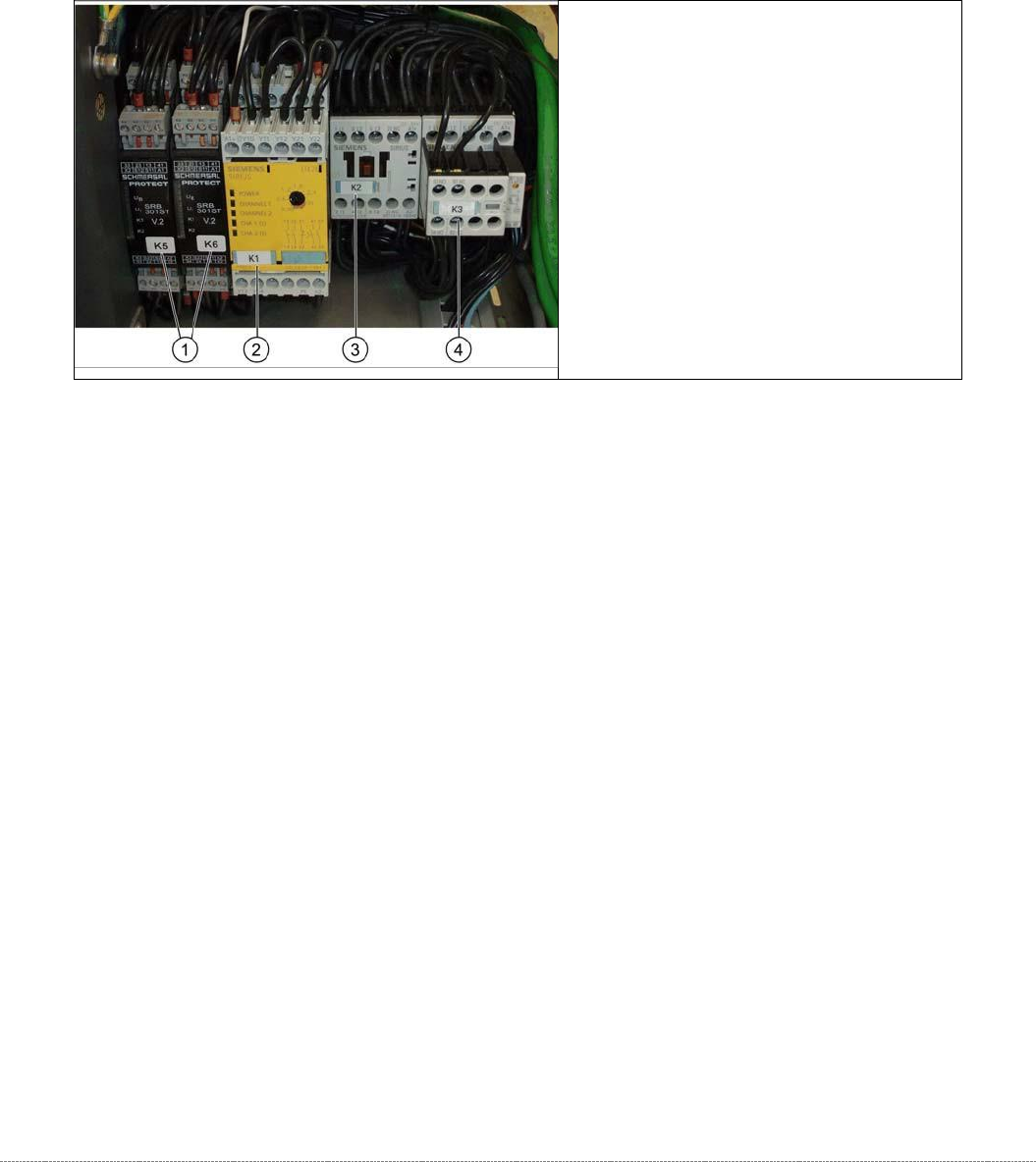
➢ Label all connections for easier installation later.
➢ Unplug all connections from K5/K6.
➢ Lever the K5/K6 off the mounting rail.
➢ Connect the new K5/K6 to the mounting rail and restore the electrical connections.
1. Protective door monitor and
emergency STOP, K5 and K6
2. SSK K1
3. Contactor K 2
4. Contactor K 3