00197471-03_Service Manual Internal WPC5_6, EN_01-2019.pdf - 第69页
Service Manual In ternal WPC5 / WPC6 Page 3- 69 3.7 Limit Sw itches, Sen sors and Light Barriers 3.7.1 Indroduction 3.7.1.1 Overvie w WPC5 Schematic location and po sition - top view WPC 5 A = Feed axis; B = Towe r (li…
Service Manual Internal WPC5 / WPC6
Page 3-68
➢ Remove all cable fixtures (cable ties etc.) and disconnect all cables and plugs from the
power supply unit.
➢ For connection details and complete circuit diagrams, please refer to the following
documentation:
➢ Detailed circuit diagrams [00196627-xx] German/English
➢ Loosen the 4 fastening screws (3), (4) and (6).
➢ Disconnect the ground terminal (5) from the mounting plate of the power supply unit.
➢ Remove the mounting plate with the complete power supply unit from the WPC, by pulling
the power supply unit out to the side.
CAUTION
! Heavy weight of the power supply !
When pulling out the mounting plate, make sure you always provide support from below as the
transformer is very heavy and the plate could bend if support is not provided.
➢ The power supply assemblies are now accessible for further service work, such as
replacement of the lines filter, rectifiers or transformers.
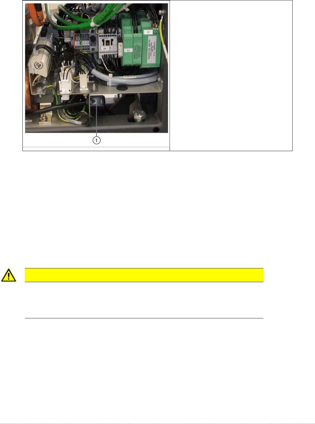
Strain relief on the power supply unit
(example of WPC6 shown)
➢ When pulling out the power supply (1),
take care of the strain relief.
Service Manual Internal WPC5 / WPC6
Page 3-69
3.7 Limit Switches, Sensors and Light Barriers
3.7.1 Indroduction
3.7.1.1 Overview
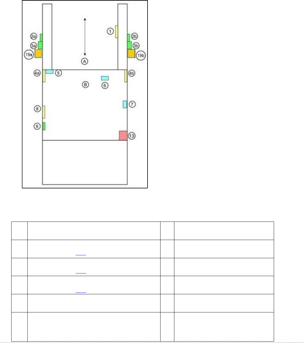
WPC5
Schematic location and position - top view WPC5
A = Feed axis; B = Tower (lift axis)
1
sensor WPTC available [03056853-xx]
6
Reference sensor, lifting axis
[03047278-xx]
2a/
2b
crash light barrier for normal components with LED
(see table on page 3-83)
7
Sensor "WPTC present in tower"
[03057841-xx]
3a/
3b
crash light barrier for high components
(see table on page 3-83)
8
Sensor "WPTC lock closed"
[03056854-xx]
19a/
19b
crash light barrier for very high components
(see table on page 3-83)
9
Reference sensor, feed axis
[03057837-xx]
4a/
4b
crash light barrier for feed axis, tower [03056927-xx]
13
Locking switch for door
5
Limit switch for lifting axis up [03047279-xx]/
limit switch for lifting axis down [03047280- -xx]
(fitted when lifting axis is down
Service Manual Internal WPC5 / WPC6
Page 3-70
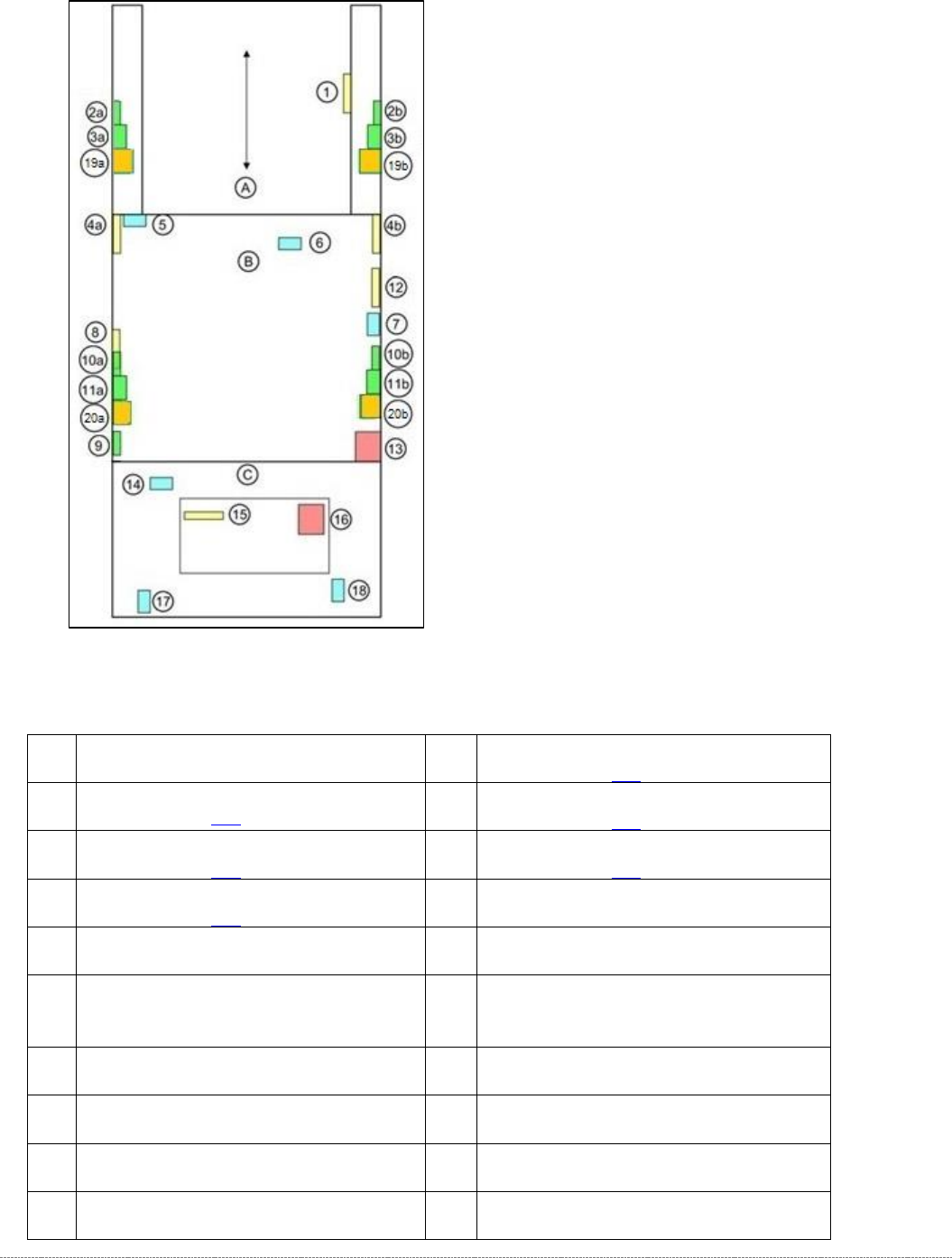
WPC6
Schematic location and position - top view WPC6
A = Feed axis; B = Tower (lifting axis); C = Loading unit
1
sensor WPTC available [03056853-xx]
10a/
10b
crash light barrier for high components, load axis
(see table on page 3-83)
2a/
2b
crash light barrier for normal components with LED
(see table on page 3-83)
11a/
11b
crash light barrier for normal components, load axis
(see table on page 3-83)
3a/
3b
crash light barrier for high components
(see table on page 3-83)
20a/
20b
crash light barrier for high components NSM
(see table on page 3-83)
19a/
19b
crash light barrier for high components NSM
(see table on page 3-83)
12
Reference sensor, feed axis
[03057837-xx]
4a/
4b
crash light barrier for feed axis, tower
[03056927-xx]
13
Locking switch for door
5
Limit switch for lifting axis up [03047279-
xx] / limit switch for lifting axis down
[03047280-xx] (fitted when lifting axis is down
14
Sensor tray detection load axis
[03056989-xx]
6
Reference sensor, lifting axis
[03047278-xx]
15
Sensor safety flap open [03056958-xx]
7
Reference point proximity switch for load
axis [03056947-xx]
16
Safety sensor hand guard [03056990-xx]
8
Sensor "WPTC present in tower"
[03057841-xx]
17
Safety sensor loading flap [03056989-xx]
9
Sensor "WPTC lock closed" [03056854-xx]
18
Sensor tray correctly inserted
[03056959-xx]