00197471-03_Service Manual Internal WPC5_6, EN_01-2019.pdf - 第83页
Service Manual In ternal WPC5 / WPC6 Page 3- 83 Spares Overview For the individual WPC types, different CO -Heights t o be adjusted. WPC4: a distinction is the setting for Standar d- and H igh- Components. Standard: 15…
Service Manual Internal WPC5 / WPC6
Page 3-82
3.7.6 Crash Light Barriers for Component Height 2 3 10 11 19 20
With the introduction of WPC5/WPC6 Version -03, new types for Crash-Light barrier component
heights are introduced.
All WPC5 and WPC6 < Serial-No.: 3xxx- exhibit LB-type 1.
All WPC5 and WPC6 > Serial-No.: 3xxx- exhibit LB-type 2 and LB-type 1.
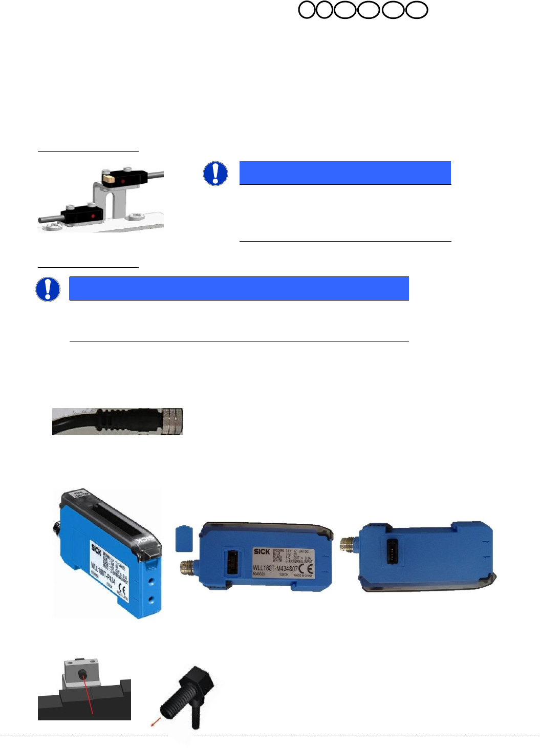
Description LB-type 1:
Description LB-type 2:
For this LB-type we have 3 spares.
1. Cable for Crash-LB CO-height,
2. Control unit LB (there are each WLL180T-M and WLL180T-F); the units are connected to each
other via a connector on the side of the unit.
3. optical fibre.
NOTICE
Spare Parts
Part numbers, see table spare parts and the
following overview.
NOTICE
Spare Parts
Part numbers, see table spare parts and the following overview.
Service Manual Internal WPC5 / WPC6
Page 3-83
Spares
Overview
For the individual WPC types, different CO-Heights to be adjusted.
WPC4: a distinction is the setting for Standard- and High- Components.
Standard: 15mm; High: 23mm.
WPC5/6 < Serial-No. 3xxx:
a distinction is the setting for Standard- and High- Components.
Standard: 15mm; High: 29mm.
Option: On WPC5 from Serial No. B1485 it is possible, in context with a „Very High Force
Pick&Place Modul (VHF-30mm/70N), to set 35mm for high components.
WPC5/6 > Serial-No. 3xxx:
a distinction is the setting for Standard-, High- and Very high- components.
Standard: 15mm; High: 32mm; Very high: 35mm (45mm Optional)
Option: In context with a „Very High Force TWIN-Head (VHF-40mm/70N), the Position Very
high components is set to 45mm.
WARNING
! DANGER of CRASH !
The Setting of 45mm requires a higher position of the gantry!.
Therefore, the 45mm can only be used with the „Twin VHF Package, 40mm, 70N with
Gantry“ (Sales number 00519986-xx)!
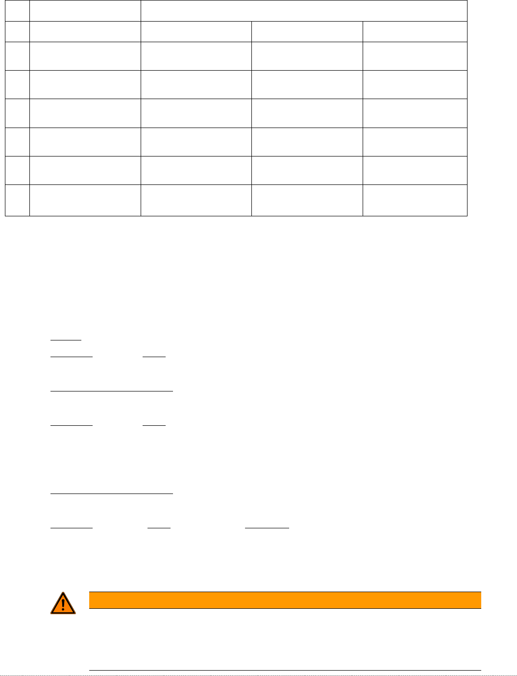
No.:
LS Type 1:
LS type 2:
Cable for Crash-LB CO Height
Control units
Fibre optic cable
2a/
2b
„Crash light barrier normal
components“
[03057282-xx]
„Crash-LS feed-axis normal
components”
[03108652-xx]
„Fibre opt.sensor WLL180T-M
preconfig SXa“
[03093294-xx]
„Fibre optic cable LL3-TV05
2m“
[03092407-xx]
3a/
3b
„Crash light barrier high
components“
[03057283-xx]
„Crash-LS feed-axis middle
compononents“
[03108654-xx]
„Fibre opt.sensor WLL180T-F
preconfig SXa“
[03093295-xx]
„Fibre optic cable LL3-TV05
2m“
[03092407-xx]
19a/
19b
„Crash-LS load-axis high
components“
[03108656-xx]
„Fibre opt.sensor WLL180T-F
preconfig SXa“
[03093295-xx]
„Fibre optic cable LL3-TV05
2m“
[03092407-xx]
10a/
10b
„Crash-LS normal components
BA“
[03057012--xx]
11a/
11b
„Crash-LS high components BA”
[03057291--xx]
„Crash-LS load-axis middel
components“
[03108658-xx]
„Fibre opt.sensor WLL180T-M
preconfig SXa“
[03093294-xx]
„Fibre optic cable LL3-TV05
2m“
[03092407-xx]
20a/
20b
„Crash-LS Beladeachse hohe
Bauteile WPC6“
[03108659-xx]
„Lichtleiter-Sensor WLL180T-F
vorprog SXa“
[03093295-xx]
„Fibre optic cable LL3-TV05
2m“
[03092407-xx]]
Table 1: Spares Overview Ligth barrier for component height.
Service Manual Internal WPC5 / WPC6
Page 3-84
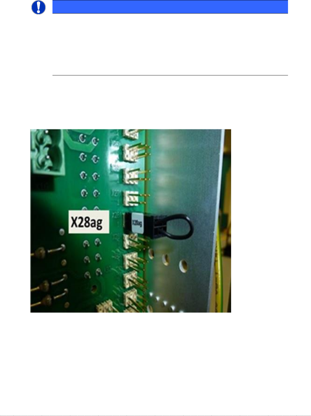
To enable the query of the third light barrier, for use on a "Very High Force TWIN-Head (VHF-
40mm/70N), a coding plug is required, which is plugged into the backplane in the control slot
on X28.
HINWEIS / NOTICE
Monitoring of the 3
rd
CO-height (very high CO’s) only with 45mm Option
The light barrier for the 3
rd
CO-height is only monitored if the coding plug, described
below, was inserted.
To avoid collisions with the sensor retainer, the 3
rd
CO level on the feed axis is set to
35mm.
At the loading axis (NSM module) this photocell is directly set to 45mm.