00197783-01_AI_Gantry-Retrofit_X-Series_S_INTERNAL_de_en.pdf - 第100页
Brief Description Required Working Time 2.4.1 Overview of Parts 100 Gantry Retrofit Portalna chrüstung
Brief Description
2.4.1 Overview of Parts Tools and Equipment Required
Gantry Retrofit Portalnachrüstung 99
2.5
2.5 Tools and Equipment Required
Tools and Equipment Required
▪ Standard tools
▪ Hose pliers
▪ Torque wrench (2 – 25 Nm) [00376625-xx] (for the trolley bearings)
▪ Depth measuring gauge 300 mm [03079617-xx]
▪ Loctite 241 [02101037-xx]
▪ Second person
The assistance of a second person is helpful for many tasks and even essential for some.
▪ Service manual HF/X-Series (internal version) [00195654-xx]
▪ Service manual for your machine [DE: 00197041-xx] [EN: 00197042-xx]
▪ When vacuum pump is installed:
Assembly instructions "Vacuum Pump SIPLACE X-Series S, SX4/DX4" [00196845-xx]
2.6
2.6 Required Working Time
Required Working Time
The complete installation will take approx. 8 hours with two people.
The new installation of the machine software, with calibration and gantry mapping, takes approx. 4
hours.
Gantry
Brief Description
Required Working Time 2.4.1 Overview of Parts
100 Gantry Retrofit Portalnachrüstung
Installation
3.1.1 Preparing the Trailing Interface Preparatory Steps
Gantry Retrofit Portalnachrüstung 101
3
3 Installation
Installation
Mark All Electrical and Pneumatic Connections Before Unplugging Them
3.1
3.1 Preparatory Steps
Preparatory Steps
3.1.1
3.1.1 Preparing the Trailing Interface
Preparing the Trailing Interface
3.1.2
3.1.2 Creating Access to the Location
Creating Access to the Location
► Move the component trolleys out of the machine.
► Switch off the machine, disconnect it from the power supply and secure it to prevent unauthorized
reactivation. Observe the instructions in section "1.2 Preparatory Work..." [ ➙ 89].
Location 2/4: creating access to the location
You may need to remove the top side cover at location 2 or 4, depending on the placement area. A dif-
ferentiation is made between locations with and without service flap:
With service flap:
NOTICE
Mark all electrical and pneumatic connections before unplugging them.
► Label all electrical and pneumatic connections before you disconnect them. Make sure that
these can be correctly assigned again later on.
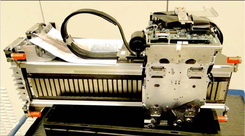
► If not prefitted: fit the trailing interface and the Vision
Hotlink Adapter to the assembly plate.
► Also fit the cable harness holder into place.
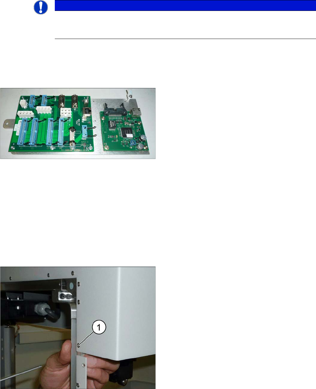
► Remove the screw (1) fastening the top end of the
outer guide.