00197783-01_AI_Gantry-Retrofit_X-Series_S_INTERNAL_de_en.pdf - 第88页
Introduction Safety information 1.1.6 Safety Instructions for the Gantry 88 Gantry Retrofit Portalna chrüstung 1.1.6 1 . 1 . 6 S a f e t y I n s t r u c t io n s f o r t h e G a n t r y Safety Instructions for the Gantry…

Introduction
1.1.4 Safety Instructions for the Power Supply Safety information
Gantry Retrofit Portalnachrüstung 87
1.1.4
1.1.4 Safety Instructions for the Power Supply
Safety Instructions for the Power Supply
Safety instructions fragment power supply - all machines without X module i.e. all machines except for SX12V2 from Nxxxx and X-series S from Hxxxx
X-Series S
▪ This means that some parts of the system carry potentially lethal voltages - even when switched off
at the main power switch.
▪ Incorrect handling of the placement system can therefore result in fatal injuries, severe injuries or
considerable damage to equipment.
▪ Measurements and maintenance work must always be carried out by appropriately qualified person-
nel.
▪ Always follow the applicable accident prevention and DIN regulations (particularly DIN EN 60 204,
part 1) or the regulations specific to your country.
▪ Before starting any maintenance work, switch the machine off at the main switch and disconnect it
from the main power supply.
▪ Always secure the machine against unauthorized reactivation. If these instructions are not followed,
you may be able to touch live parts, which could result in fatal or severe injuries.
Maintaining, Installing or Removing Assemblies
► End all placement operations on the machine.
► Shut down the Windows operating system correctly, otherwise problems may occur when restarting
or data may be lost.
► Switch the machine off at the main switch.
► Disconnect the machine from the main power supply.
► Switch off the machine and attach warnings signs to indicate that service work is in progress.
1.1.5
1.1.5 Safety Instructions for the Compressed Air Supply
Safety Instructions for the Compressed Air Supply
Risk of injury from compressed air
Prolonge d interruptions to the compressed air supply can cause d amage
NOTICE
SIPLACE X-Series S up to machine no.: Gxxxx
This section applies to machines of type SIPLACE X-Series S up to machine no. Gxxxx without
SMPS power supply.
DANGER
Hazardous Voltages!
The machine is supplied with 3 x 400 V~ (or 3 x 204 V~ / 3 x 220 V~ / 3 x 230 V~ / 3 x 380 V~
/ 3 x 415 V~) ± 5 %, 50/60 Hz mains voltages.
► Observe the safety instructions in the user manual during all service work!
► Before you start working on the power supply, check it for absence of voltage and observe
the waiting times!
CAUTION
Risk of injury from compressed air!
Risk of injury when disconnecting the compressed air lines.
► NEVER disconnect compressed air lines while they are still pressurized.
CAUTION
Prolonged interruptions to the compressed air supply can cause damage.
When the machine is switched on, do not use the shutoff valve to interrupt the compressed air
supply for more than 30 minutes.
► If you need to shut off the compressed air system for longer in order to carry out your work,
you must switch the placement system off at the main switch and disconnect it from the
power supply.
Introduction
Safety information 1.1.6 Safety Instructions for the Gantry
88 Gantry Retrofit Portalnachrüstung
1.1.6
1.1.6 Safety Instructions for the Gantry
Safety Instructions for the Gantry
1.1.7
1.1.7 Safety Instructions on Hazardous Materials
Safety Instructions on Hazardous Materials
1.1.8
1.1.8 Classification of the Optical Systems
Classification of the Optical Systems
1.1.8.1
1.1.8.1 Classification of the Whole Machine
Classification of the Whole Machine
1.1.8.2
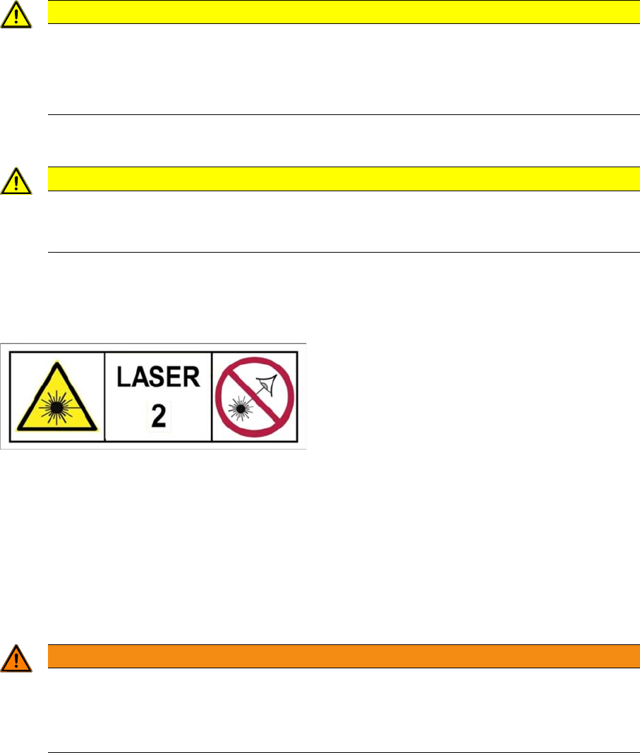
1.1.8.2 Laser Classification
Laser Classification
The following modules are assigned to the laser class 2:
▪ PCB barcode scanner
▪ Component sensor on the SpeedStar
▪ Component sensor on the MultiStar
▪ Laser light barriers at the board conveyor
1.1.8.3
1.1.8.3 Classification of the Camera Systems
Classification of the Camera Systems
CAUTION
Moving the gantry can damage the placement head.
When moving the gantry, observe the following:
► NEVER move the gantry by pushing with your hands against the placement head.
► NEVER push the gantry while the Z axis is lowered.
CAUTION
Observe the safety data sheets
Observe the applicable safety data sheet, when handling hazardous materials (e. g. Loctite
241, ethanol).
The ready-to-operate overall machine is assigned to
laser class 2.
The laser classes are determined according to DIN
EN 60825-1:2014.
WARNING
LEDs
The camera illumination systems are fitted with light LEDs. These are assigned to risk group 1
according to IEC 62741:2006.
► Do not look into beam!
Introduction
1.1.8 Classification of the Optical Systems Preparatory Work...
Gantry Retrofit Portalnachrüstung 89
1.2
1.2 Preparatory Work...
Preparatory Work...
Purpose and Scope
Before performing any preventive maintenance work, conversion work or service work, a procedure of
locking and tagging must be followed and warning signs must be attached if not stated otherwise. If it is
not necessary to switch off the machine, it is explicitly mentioned.
The procedure, when followed correctly, eliminates the possibility of an employee being injured.
Description
Whenever it becomes necessary to isolate, control and release energy, the following procedure is to be
followed.
► Notify affected employees.
► Switch off the machine and all additional devices. Carry out all normal stopping procedures:
⇨ Press the STOP button.
⇨ Shut down the station computer.
⇨ Switch the machine off at the main switch.
► Isolate the machine from all its energy sources:
⇨ Shut off the compressed air supply.
⇨ Shut off the main power supply.
► Lock out the machine.
⇨ Attach a lock wherever possible (e.g. to the main power switch).
NOTICE
Additional safety measures
These procedures represent the minimum lock/tag out requirements for the machine during
preventive maintenance work and service work. Any additional safeguards needed to complete
work safely can be specified by facilities supervision, the safety officer, the safety committee
and the health department.
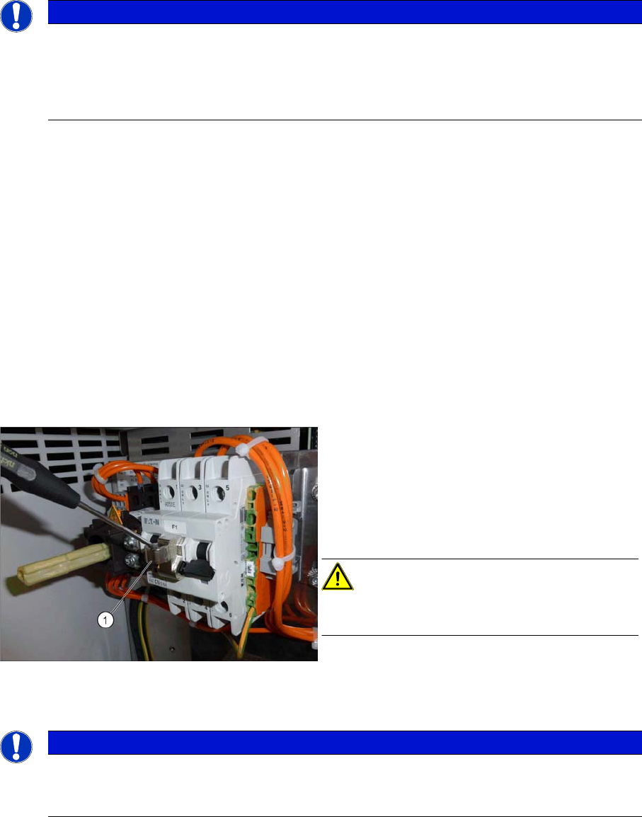
Attaching the lockout attachment Z-IS/SPE-1TE
[03123101-xx]
Example: Securing the machine with a lockout at-
tachment
The lockout attachment can prevent the machine
from being switched on inadvertently.
► Switch off the machine.
► Set the circuit breaker to OFF.
CAUTION!
The lockout attachment may only be attached when
the machine is switched off!
► Attach the lockout attachment (1) to the circuit
breaker.
► Secure the circuit breaker with a padlock.
NOTICE
Lockout attachment in the service box of your machine
On machines that are delivered from June 2016, the lockout attachment [03123101-xx] is lo-
cated in the service box.