00197783-01_AI_Gantry-Retrofit_X-Series_S_INTERNAL_de_en.pdf - 第120页
Installation Fitting the Y Trailing Cable for Gantry 1/3 3.1.4 Removing the Top Cove r 120 Gantry Retrofit Portalna chrüstung ► Further installation is performe d by following the above instru ctions in the reverse order…
Installation
3.1.4 Removing the Top Cover Fitting the Y Trailing Cable for Gantry 1/3
Gantry Retrofit Portalnachrüstung 119
3.6
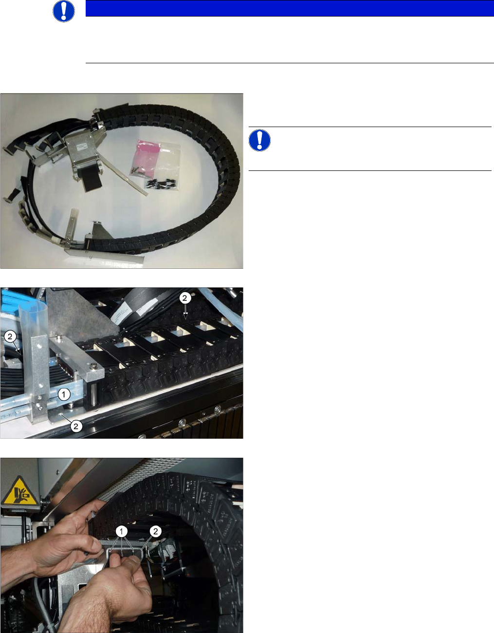
3.6 Fitting the Y Trailing Cable for Gantry 1/3
Fitting the Y Trailing Cable for Gantry 1/3
► If any white hoses were damaged during removal, cut these with hose cutters.
NOTICE
Recommendation: rubber gloves
The hoses are very smooth.
► We recommend using rubber gloves for better handling.
► Remove the "goose neck" and the three sealed
screws on the new trailing cable.
NOTICE!
This will still be on any gantry which is already present.
► Place the trailing cable into the machine.
► Fit the white hoses (1) to the lower trailing cable.
► Fasten the lower trailing cable with the three fasten-
ing screws (2) and Loctite 241.
► Fit all flat ribbon cables to the trailing interface and
the six black hoses. See also "4.1.1 Replacing the
Trailing Cable" [ ➙ 131].
► Fasten the upper trailing cable with the three
screws (1) to the goose neck (2). Secure the screws
with Loctite 241.
Installation
Fitting the Y Trailing Cable for Gantry 1/3 3.1.4 Removing the Top Cover
120 Gantry Retrofit Portalnachrüstung
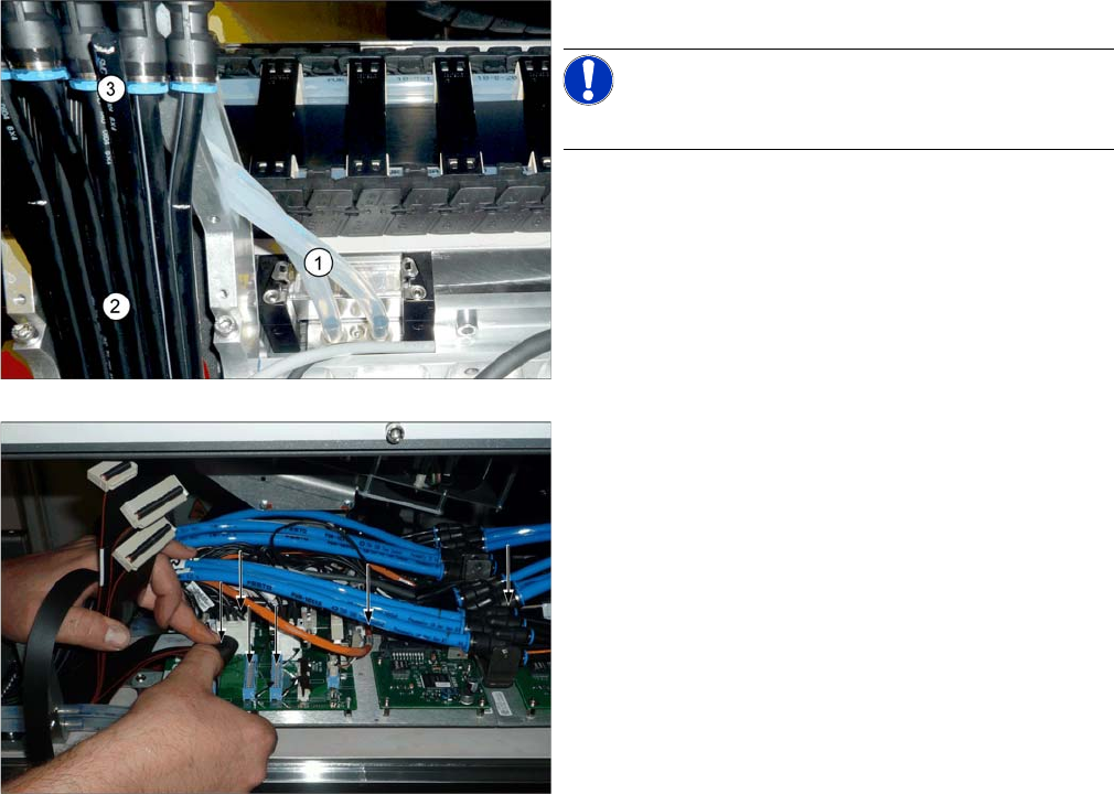
► Further installation is performed by following the above instructions in the reverse order. Also read
section "4.1.1.3 Replacing the Y Trailing Cable" [ ➙ 137].
► Attach the white (1) and black hoses (2) to the gantry.
NOTICE!
The 3rd black hose (3) serves as a spare and is not used.
► Reconnect the electrical and pneumatic systems to
the trailing interface.
► Connect the divided flat ribbon cable to the Vision
Hotlink Adapter, with one section on the trailing inter-
face and the other section on the Vision Hotlink
Adapter (from the back).
Installation
3.1.4 Removing the Top Cover Fitting the Y Trailing Cable for the New Gantry 2/4
Gantry Retrofit Portalnachrüstung 121
3.7
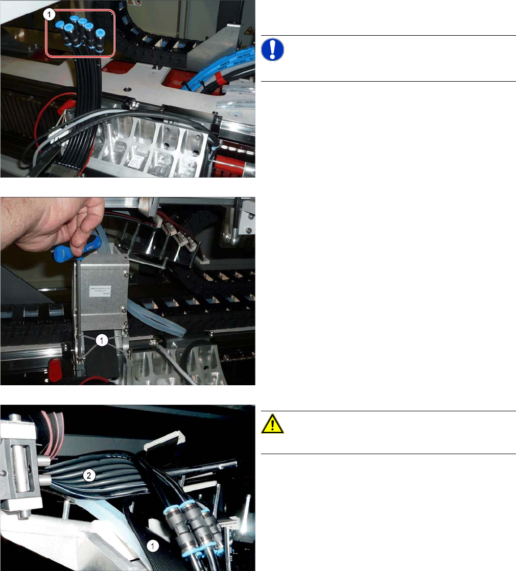
3.7 Fitting the Y Trailing Cable for the New Gantry 2/4
Fitting the Y Trailing Cable for the New Gantry 2/4
► Position the hose couplings (1) on the black hoses on
the gantry.
NOTICE!
The third hose remains free. This serves as a spare.
► Carefully place the new trailing cable into the ma-
chine.
► Fasten the goose neck to the gantry, with the four
screws (1). Secure the screws with Loctite 241.
CAUTION!
Do not bend the cable or hoses!
► Run the flat ribbon cable (1) from the gantry to the Y
gantry interface. Run the cable with a 90 degrees ro-
tation.
► Run the black hoses (2) from the trailing cable to the
connections on the gantry. Run the cables with a 90
degrees rotation.