00197783-01_AI_Gantry-Retrofit_X-Series_S_INTERNAL_de_en.pdf - 第140页
Appendix Excerpts from the Service Manual 4.1.2 Overview of GCUs 140 Gantry Retrofit Portalna chrüstung 4.1.2 4 . 1 . 2 O v e r v ie w o f G C U s Overview of GCUs Overview GCUs

Appendix
4.1.1 Replacing the Trailing Cable Excerpts from the Service Manual
Gantry Retrofit Portalnachrüstung 139
Installation
► Installation is performed by following the above instructions in the reverse order. Also observe the
following instructions:
CAUTION
Always handle the trailing cable with care
► If a vacuum pump is fitted, also observe the relevant assembly instructions [00196845-xx].
► Always handle the new trailing cable with care.
► You might need to enlist the help of a second person.
► Make sure that the flat ribbon cable and the pneumatic hoses are not rubbed against any
parts or folded. Look out for sharp edges.
► Prepare the trailing cable. Place the old and new trailing cables next to one another and
match the length of the new trailing cable hose to the old one.
► For production reasons, the new trailing cable is supplied with a holder. This new holder
can be dismantled before installation and the holder already in the machine can be used
again.
► If you use the new holder, you will need to dismantle all attached items (boards etc.) from
the old holder and attach them to the new holder.
► If hose ends were damaged during removal, cut these with hose cutters.
► Clean the trailing cable contact surface on the machine base with a dry cloth.
► Carefully insert the new trailing cable into the prescribed position. Make sure you do not fold
or twist the trailing cable.
► Check that the power track chain runs parallel to the machine base. Move the gantry back
and forth.
► If it is difficult to push the hoses onto the tubes, moisten these first with white spirits or iso-
propanol.
► Secure with screws with Loctite 241.
Appendix
Excerpts from the Service Manual 4.1.2 Overview of GCUs
140 Gantry Retrofit Portalnachrüstung
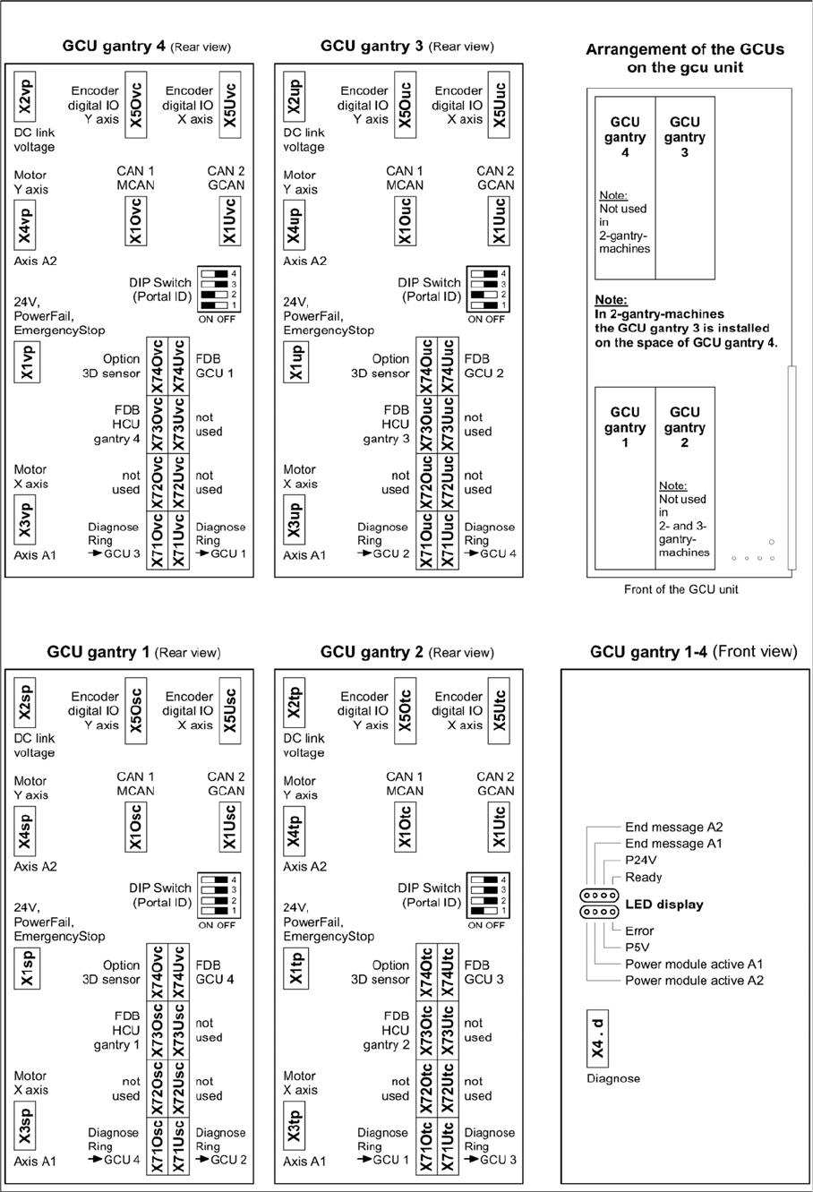
4.1.2
4.1.2 Overview of GCUs
Overview of GCUs
Overview GCUs

Appendix
4.1.2 Overview of GCUs Excerpts from the Service Manual
Gantry Retrofit Portalnachrüstung 141
DIP switch (gantry ID)
LEDs
Switch Status Signal name Description
GCU1 GCU2 GCU3 GCU4
S1.1 ON/OFF Gantry_ID_0 OFF ON OFF ON
S1.2 ON/OFF Gantry_ID_1 OFF OFF ON ON
S1.3 ON/OFF Gantry_ID_2 OFF OFF OFF OFF
S1.4 ON/OFF Gantry_ID_3 OFF OFF OFF OFF
LED Color Status Signal name Description
H1 RD ON LED_ERROR Error display
H2 GN ON A1_LED_PM_ON_N Power module activated, axis 1
H3 GN ON A2_LED_PM_ON_N Power module activated, axis 2
H4 GN ON A1_LED_END End position signal, axis 1
H5 GN ON A2_LED_END End position signal, axis 2
H6 GN ON LED_READY Ready
H7 GN ON P24V +24VDC
H8 GN ON P5V +5VDC