00197783-01_AI_Gantry-Retrofit_X-Series_S_INTERNAL_de_en.pdf - 第118页
Installation Fitting the Gantry 3.1.4 Removing the Top Cover 118 Gantry Retrofit Portalna chrüstung ► Fit the buffer holder with the three f astening screws (1) . Make sure that this is exactly vertical. Tighten the thre…
Installation
3.1.4 Removing the Top Cover Fitting the Gantry
Gantry Retrofit Portalnachrüstung 117
3.5
3.5 Fitting the Gantry
Fitting the Gantry
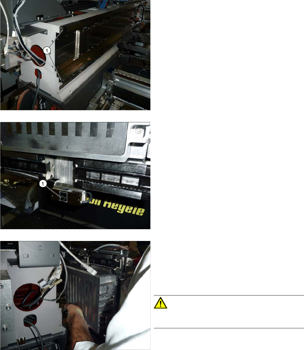
► Remove the buffer holder and the plastic covers (1)
on both rails.
► Loosen the 16 screws fastening the four trolleys to
the gantry. The four trolleys must then have room for
movement.
► Remove the protective foil (1) on the incremental en-
coder on the gantry.
When installing the gantry, you either need a gantry lift or
the help of a second person.
► Lift the gantry onto the guide rails.
► Position the gantry as exactly as possible and then
push it carefully onto the rails. This presses the plas-
tic sleeves in the trolley bearing out.
CAUTION!
Do not pull the gantry backwards. This could cause balls
to fall out of the trolley bearings.
Installation
Fitting the Gantry 3.1.4 Removing the Top Cover
118 Gantry Retrofit Portalnachrüstung
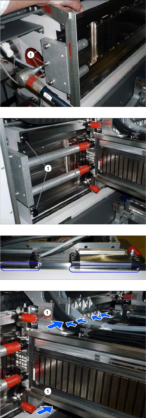
► Fit the buffer holder with the three fastening
screws (1). Make sure that this is exactly vertical.
Tighten the three fastening screws with a torque of
24.7 Nm.
► Fit the long buffer (1).
► Fit the two plastic covers on the ends of the guide
rails (2).
► Check the gap between the trolley and the guide rails.
This should be the same at all points.
► Tighten the 16 fastening screws (1) with a torque of
9.5 Nm.
Always tighten all four screws in the row. Start with
the top row and work your way downwards.
► Tighten the 16 fastening screws again to check them,
using a torque of 9.5 Nm.
Installation
3.1.4 Removing the Top Cover Fitting the Y Trailing Cable for Gantry 1/3
Gantry Retrofit Portalnachrüstung 119
3.6
3.6 Fitting the Y Trailing Cable for Gantry 1/3
Fitting the Y Trailing Cable for Gantry 1/3
► If any white hoses were damaged during removal, cut these with hose cutters.
NOTICE
Recommendation: rubber gloves
The hoses are very smooth.
► We recommend using rubber gloves for better handling.
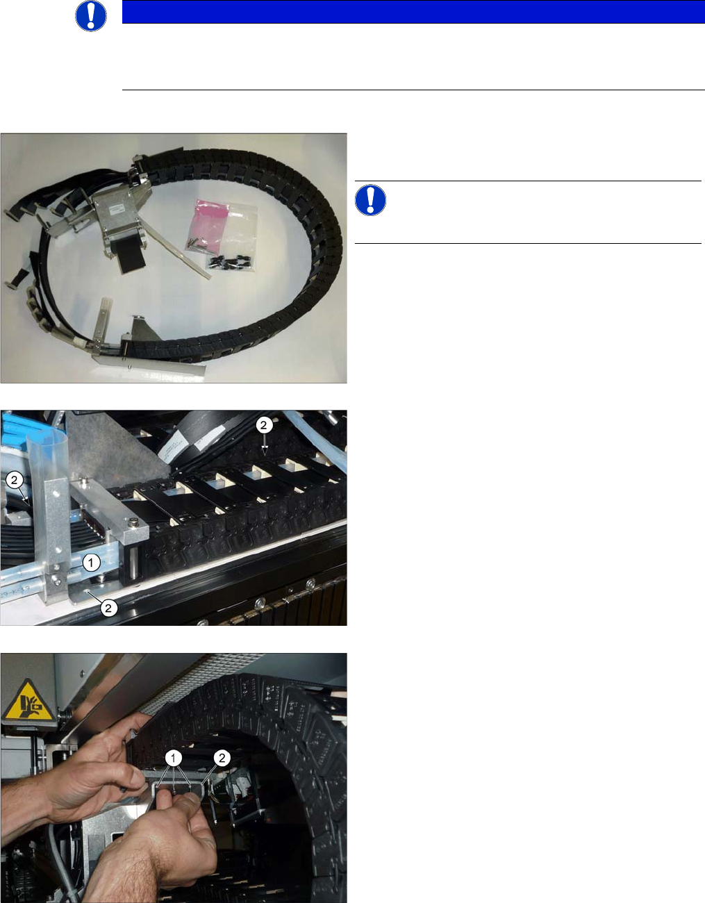
► Remove the "goose neck" and the three sealed
screws on the new trailing cable.
NOTICE!
This will still be on any gantry which is already present.
► Place the trailing cable into the machine.
► Fit the white hoses (1) to the lower trailing cable.
► Fasten the lower trailing cable with the three fasten-
ing screws (2) and Loctite 241.
► Fit all flat ribbon cables to the trailing interface and
the six black hoses. See also "4.1.1 Replacing the
Trailing Cable" [ ➙ 131].
► Fasten the upper trailing cable with the three
screws (1) to the goose neck (2). Secure the screws
with Loctite 241.