00197783-01_AI_Gantry-Retrofit_X-Series_S_INTERNAL_de_en.pdf - 第142页
Appendix Excerpts from the Service Manual 4 .1.3 Replacing the Y Axis Incr emental Encoder [03094996-xx] 142 Gantry Retrofit Portalna chrüstung 4.1.3 4 . 1 . 3 R e p la c in g t h e Y A x is I n c r e m e n t a l E n c o…

Appendix
4.1.2 Overview of GCUs Excerpts from the Service Manual
Gantry Retrofit Portalnachrüstung 141
DIP switch (gantry ID)
LEDs
Switch Status Signal name Description
GCU1 GCU2 GCU3 GCU4
S1.1 ON/OFF Gantry_ID_0 OFF ON OFF ON
S1.2 ON/OFF Gantry_ID_1 OFF OFF ON ON
S1.3 ON/OFF Gantry_ID_2 OFF OFF OFF OFF
S1.4 ON/OFF Gantry_ID_3 OFF OFF OFF OFF
LED Color Status Signal name Description
H1 RD ON LED_ERROR Error display
H2 GN ON A1_LED_PM_ON_N Power module activated, axis 1
H3 GN ON A2_LED_PM_ON_N Power module activated, axis 2
H4 GN ON A1_LED_END End position signal, axis 1
H5 GN ON A2_LED_END End position signal, axis 2
H6 GN ON LED_READY Ready
H7 GN ON P24V +24VDC
H8 GN ON P5V +5VDC
Appendix
Excerpts from the Service Manual 4.1.3 Replacing the Y Axis Incremental Encoder [03094996-xx]
142 Gantry Retrofit Portalnachrüstung
4.1.3
4.1.3 Replacing the Y Axis Incremental Encoder [03094996-xx]
Replacing the Y Axis Incremental Encoder [03094996-xx]
Parts, equipment and tools
▪ Select the correct incremental encoder:
▪ If needed, mounting bracket for Y axis sensor [03086842-xx]
▪ Test device PG1-I (MS22/MS30) assembly [03102699-xx]
▪ Ethanol
Isopropanol – IPA can be used as an alternative.
Overview
Removal
► Unplug the incremental encoder press-fit connection from the gantry interface. In this case, make a
note of the position, to make clear assignment easier later on.
► Unthread the connection cable as far as the incremental encoder.
► Loosen the three screws fastening the incremental encoder holder and carefully remove this togeth-
er with the incremental encoder.
X4i S, X4 S, X3 S, X2 S X4i S micron, X4 S micron
Read head MS22.84 Y axis [03094996-xx] (includ-
ing plastic thickness gauge)
RSF MS30.53 MK read head Y axis [03102065-xx]
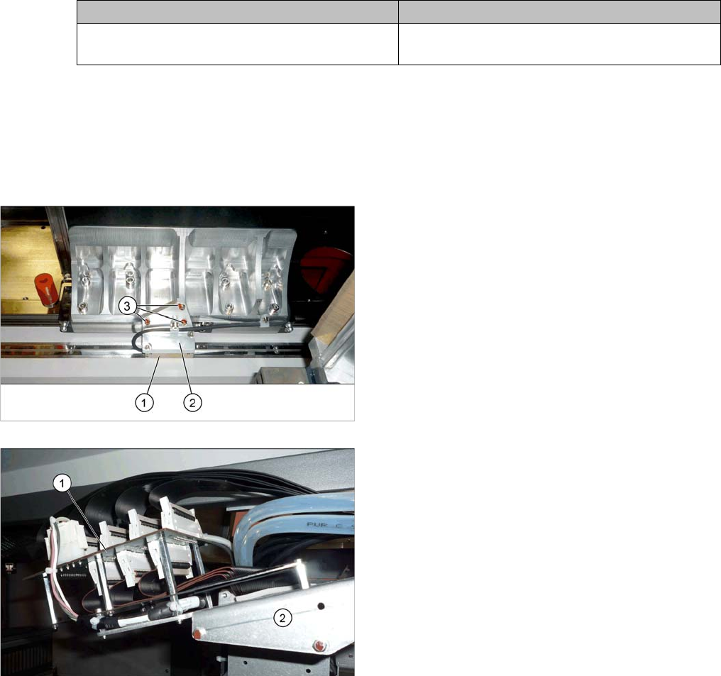
1. Incremental encoder (mounted on the holder)
2. Holder
3. Fastening screws (3x) for holder
1. Gantry interface
2. Trailing cable holder on gantry

Appendix
4.1.4 Track Signals and Zero Pulse Excerpts from the Service Manual
Gantry Retrofit Portalnachrüstung 143
Installation
► Clean the reading surface of the incremental encoder with a cloth and ethanol or with a Q tip.
► Fit the incremental encoder with the three fastening screws. To do this, place the thickness gauge
provided between the incremental encoder and the scale, so that there is a gap. This gap must either
be 0.4 mm (golden scale) or 0.75 mm (black-white). Use the corresponding thickness gauge (plas-
tic).
► Reconnect to the electricity supply.
► Check the track signals with the testing device. (See "4.1.4 Track Signals and Zero Pulse" [ ➙ 143])
4.1.4
4.1.4 Track Signals and Zero Pulse
Track Signals and Zero Pulse
Check
Proceed as follows to check the zero pulse.
► Switch off the machine.
► Unplug the incremental encoder from the head board or the gantry interface and connect it to the
test device. (See "4.1.4.1 Test Device PG1-I (MS22/MS30) [03102699-xx] – Operation" [ ➙ 144])
► Move the head or gantry manually back and forth. This movement enables you to read the correct
track signal progress from the test device.
► If the track signal is not within the tolerance range, you will need to reset the incremental encoder.
The incremental encoder has then been fitted either too near, too far away, inclined and/or displaced.
CAUTION
Make sure that the cables do not rub against anything.
Make sure that the axes can be moved without damaging the cables.
► Fasten them with cable ties.