00197783-01_AI_Gantry-Retrofit_X-Series_S_INTERNAL_de_en.pdf - 第113页
Installation 3.1.4 Removing the Top Cover Fitting the Trailing Interface Boards Gantry Retrofit Portalnachrüstung 113 3.4 3 . 4 F it t in g t h e T r a ilin g I n t e r f a c e B o a r d s Fitting the Trailing Interface …
Installation
Preparing the Cable and Hoses 3.1.4 Removing the Top Cover
112 Gantry Retrofit Portalnachrüstung
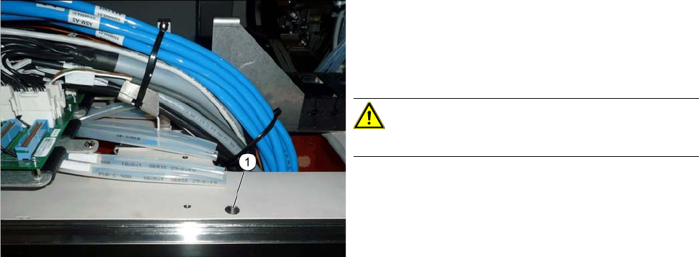
► Shorten the white hoses on both sides, level with the
large hole (1).
If possible, also shorten white hoses which have al-
ready been used. This removes any damaged sec-
tions of the hoses.
CAUTION!
Do not shorten the black hoses.
Installation
3.1.4 Removing the Top Cover Fitting the Trailing Interface Boards
Gantry Retrofit Portalnachrüstung 113
3.4
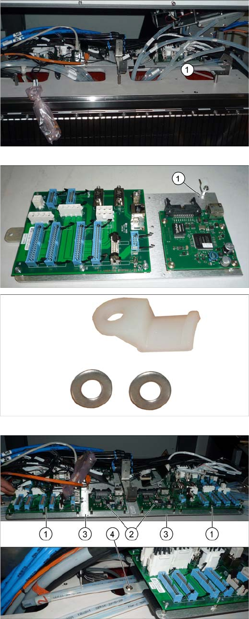
3.4 Fitting the Trailing Interface Boards
Fitting the Trailing Interface Boards
► Fit the third spacer bolt (1).
► Check whether the strain relief (1) for the hotlink ca-
ble (top right in the diagram) is present at all points.
► If required, add more strain relief (1x spacer bolt, 2x
washer and 1x plastic strain relief each). Secure the
strain relief with Loctite 241.
► Fit the two trailing interface boards (1) and the two Vi-
sion Hotlink Adapters (2), together with the assembly
plates (3).
Each assembly plate is fastened with an outer (4) and
a joint inner screw.
Make sure that the white hoses are run correctly (in
pairs on the left and right under the assembly plate).
Installation
Fitting the Trailing Interface Boards 3.1.4 Removing the Top Cover
114 Gantry Retrofit Portalnachrüstung
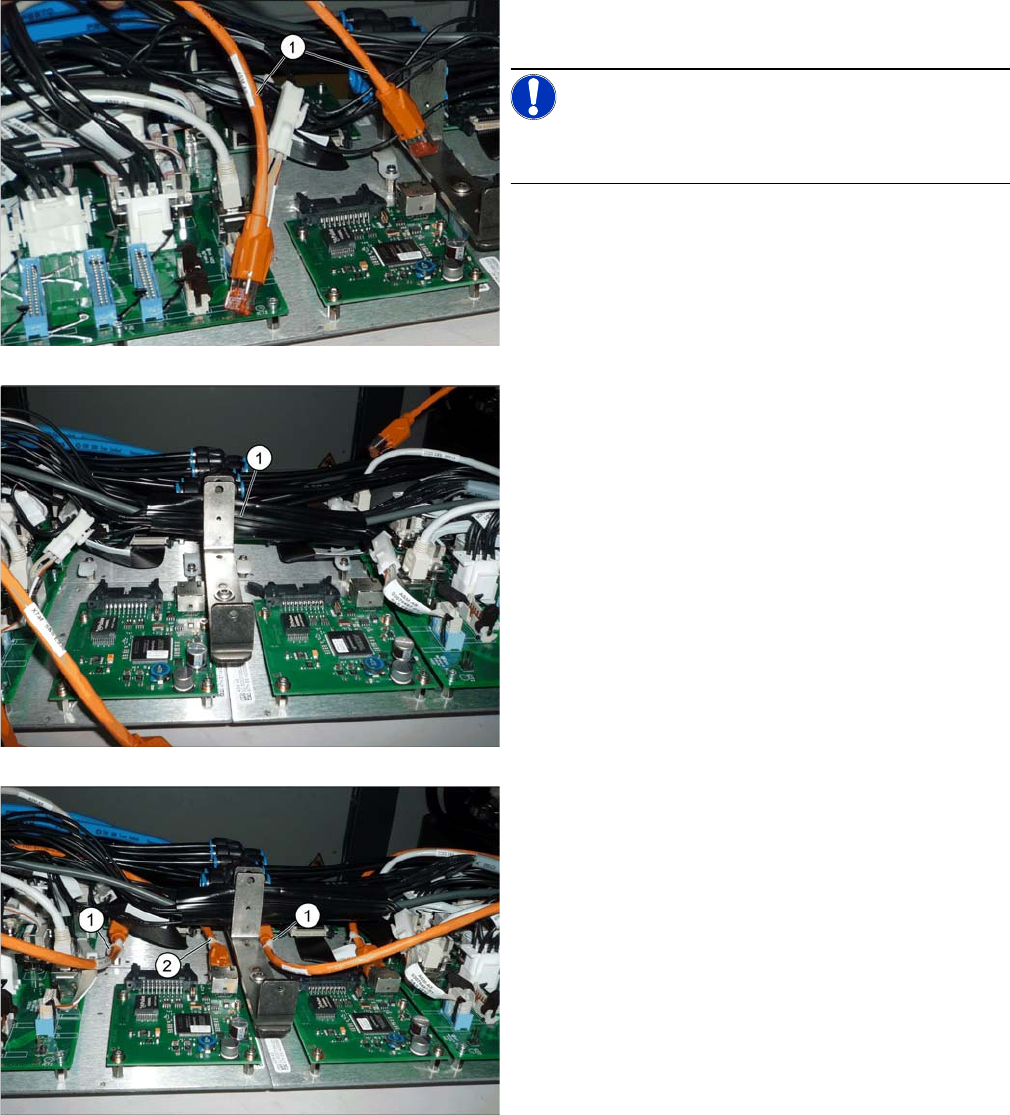
► First, establish all connections to the trailing interface,
at the machine end.
NOTICE!
We recommend that you connect the orange hotlink
cable (1) later on.
► Bind together all cables running through the middle
[03076516-xx (with X13ba and X14ba) and
[03076477-xx] (voltage for Vision Hotlink Adapter)
with a zipper hose (1) and stow these away between
the two vertical holders.
► Connect the hotlink cables (1) and (2) and fasten this
with cable ties to the cable harness holder.