00197783-01_AI_Gantry-Retrofit_X-Series_S_INTERNAL_de_en.pdf - 第101页
Installation 3.1.1 Preparing the Trailing Interf ace Preparatory Steps Gantry Retrofit Portalnachrüstung 101 3 3 I n s t a lla t io n Installation Mark Al l Electrical and Pneumatic Connec tions Before Un plugging Them 3…
Brief Description
Required Working Time 2.4.1 Overview of Parts
100 Gantry Retrofit Portalnachrüstung
Installation
3.1.1 Preparing the Trailing Interface Preparatory Steps
Gantry Retrofit Portalnachrüstung 101
3
3 Installation
Installation
Mark All Electrical and Pneumatic Connections Before Unplugging Them
3.1
3.1 Preparatory Steps
Preparatory Steps
3.1.1
3.1.1 Preparing the Trailing Interface
Preparing the Trailing Interface
3.1.2
3.1.2 Creating Access to the Location
Creating Access to the Location
► Move the component trolleys out of the machine.
► Switch off the machine, disconnect it from the power supply and secure it to prevent unauthorized
reactivation. Observe the instructions in section "1.2 Preparatory Work..." [ ➙ 89].
Location 2/4: creating access to the location
You may need to remove the top side cover at location 2 or 4, depending on the placement area. A dif-
ferentiation is made between locations with and without service flap:
With service flap:
NOTICE
Mark all electrical and pneumatic connections before unplugging them.
► Label all electrical and pneumatic connections before you disconnect them. Make sure that
these can be correctly assigned again later on.
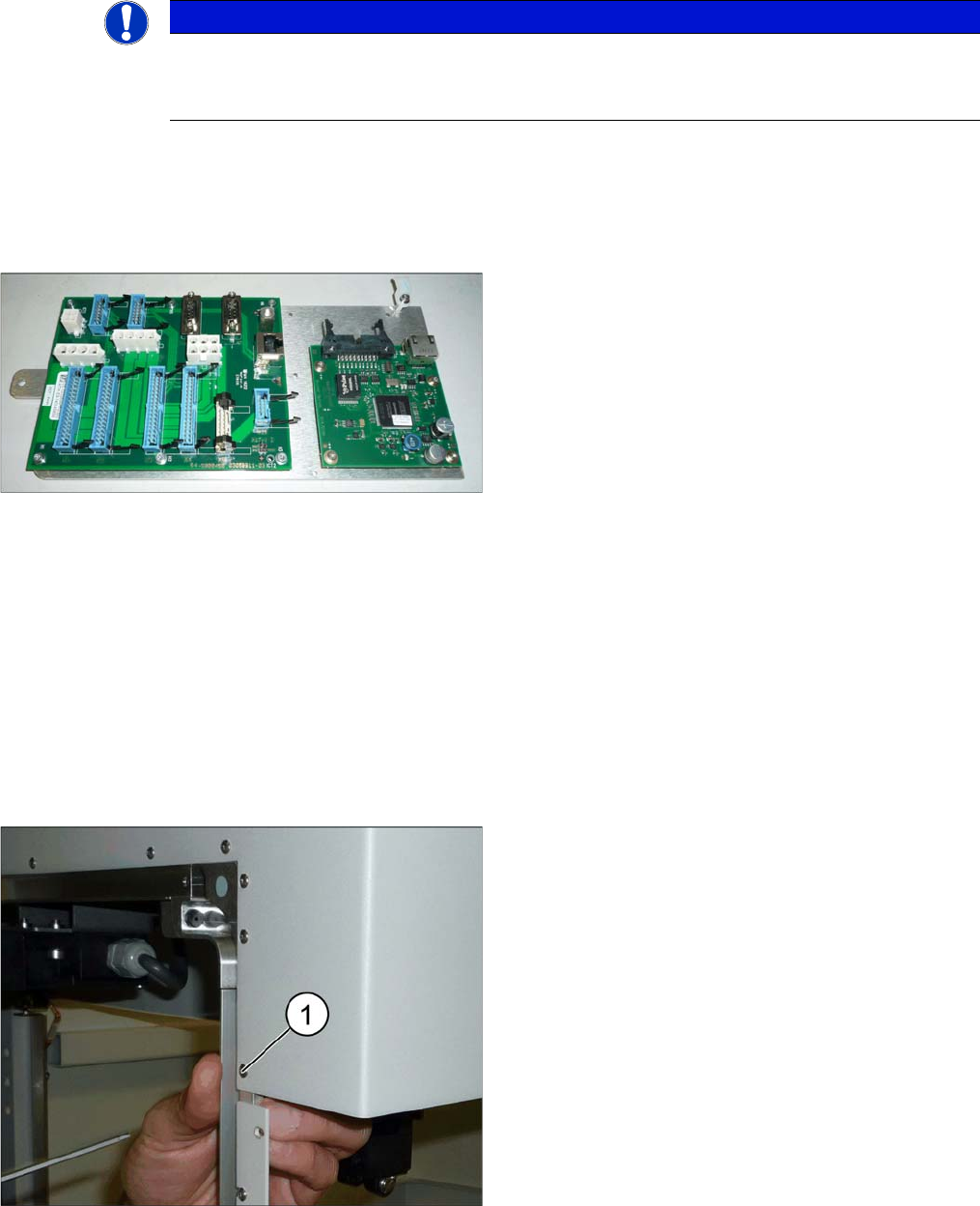
► If not prefitted: fit the trailing interface and the Vision
Hotlink Adapter to the assembly plate.
► Also fit the cable harness holder into place.
► Remove the screw (1) fastening the top end of the
outer guide.
Installation
Preparatory Steps 3.1.2 Creating Access to the Location
102 Gantry Retrofit Portalnachrüstung
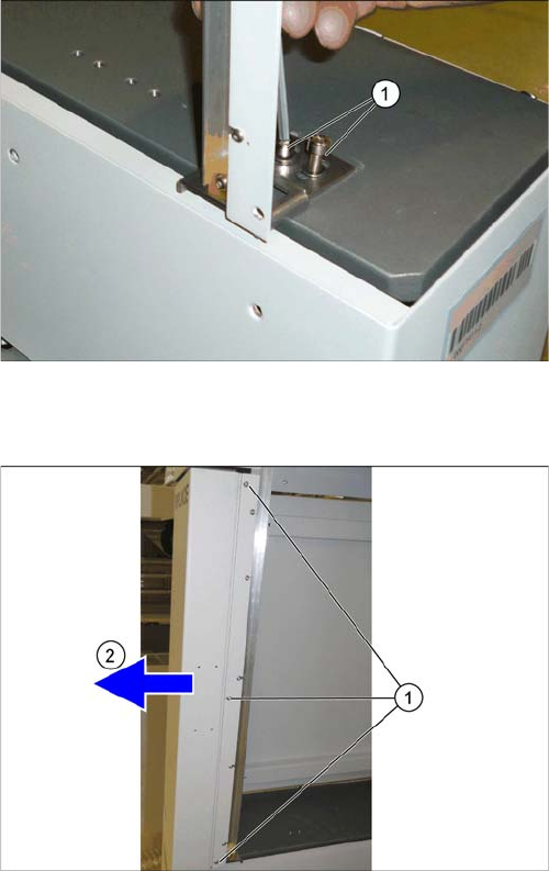
Without service flap:
► Remove the two screws (1) fastening the lower end
of the outer guide and remove the guide.
► Remove the three captive screws (1).
► Pull the side cover forwards and out (2).