00197783-01_AI_Gantry-Retrofit_X-Series_S_INTERNAL_de_en.pdf - 第145页
Appendix 4.1.4 Track Signals and Zero Pulse Excerpts from the Service Manual Gantry Retrofit Portalnachrüstung 145
Appendix
Excerpts from the Service Manual 4.1.4 Track Signals and Zero Pulse
144 Gantry Retrofit Portalnachrüstung
4.1.4.1
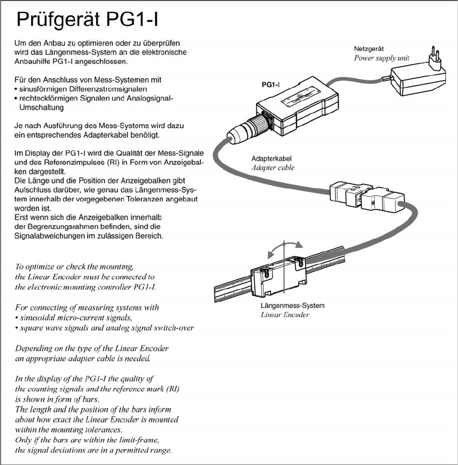
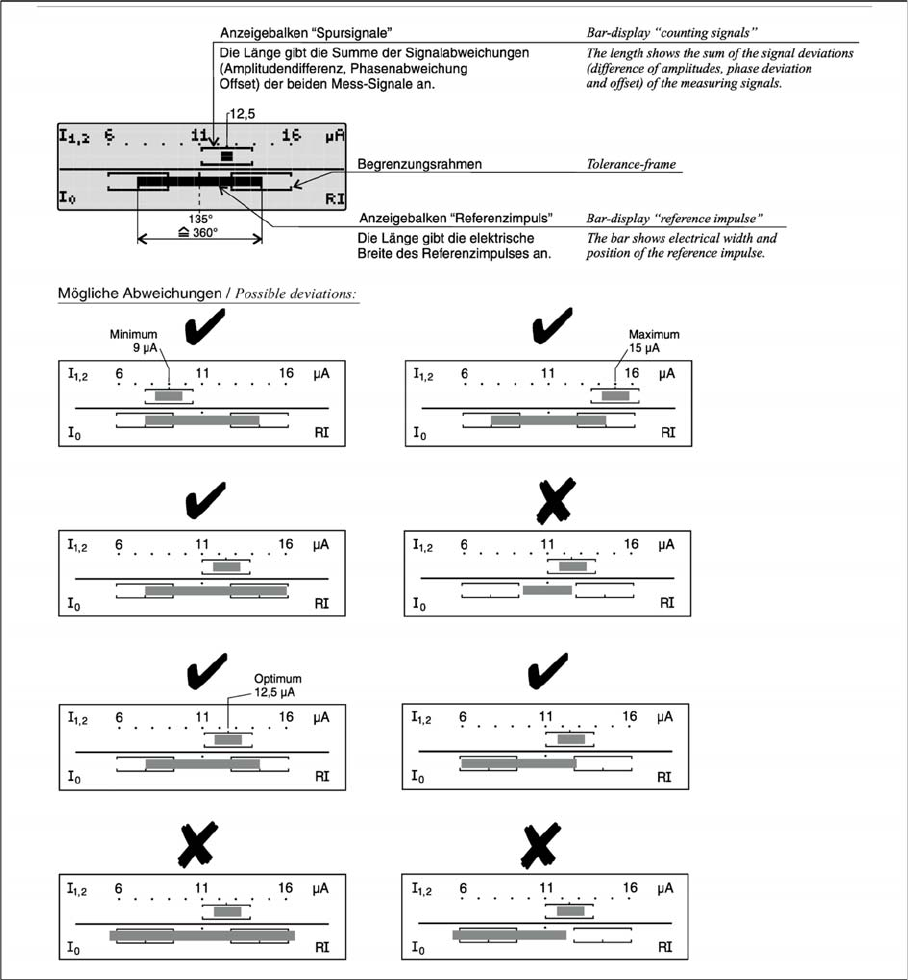
4.1.4.1 Test Device PG1-I (MS22/MS30) [03102699-xx] – Operation
Test Device PG1-I (MS22/MS30) [03102699-xx] – Operation
Appendix
4.1.4 Track Signals and Zero Pulse Excerpts from the Service Manual
Gantry Retrofit Portalnachrüstung 145
Appendix
Excerpts from the Service Manual 4.1.5 Dismantling the Lower Side Cover
146 Gantry Retrofit Portalnachrüstung
4.1.5
4.1.5 Dismantling the Lower Side Cover
Dismantling the Lower Side Cover
Most tasks performed on the pneumatic system require that you dismantle the lower side cover for the
relevant location.
Parts, equipment and tools
▪ Shortened Allen key, if required
Dismantling the side cover
Dismantling the Lower Side Cover – X34iS
Fitting the side cover
► Assembly is performed by following the above instructions in the reverse order.
Loosening the lower side cover
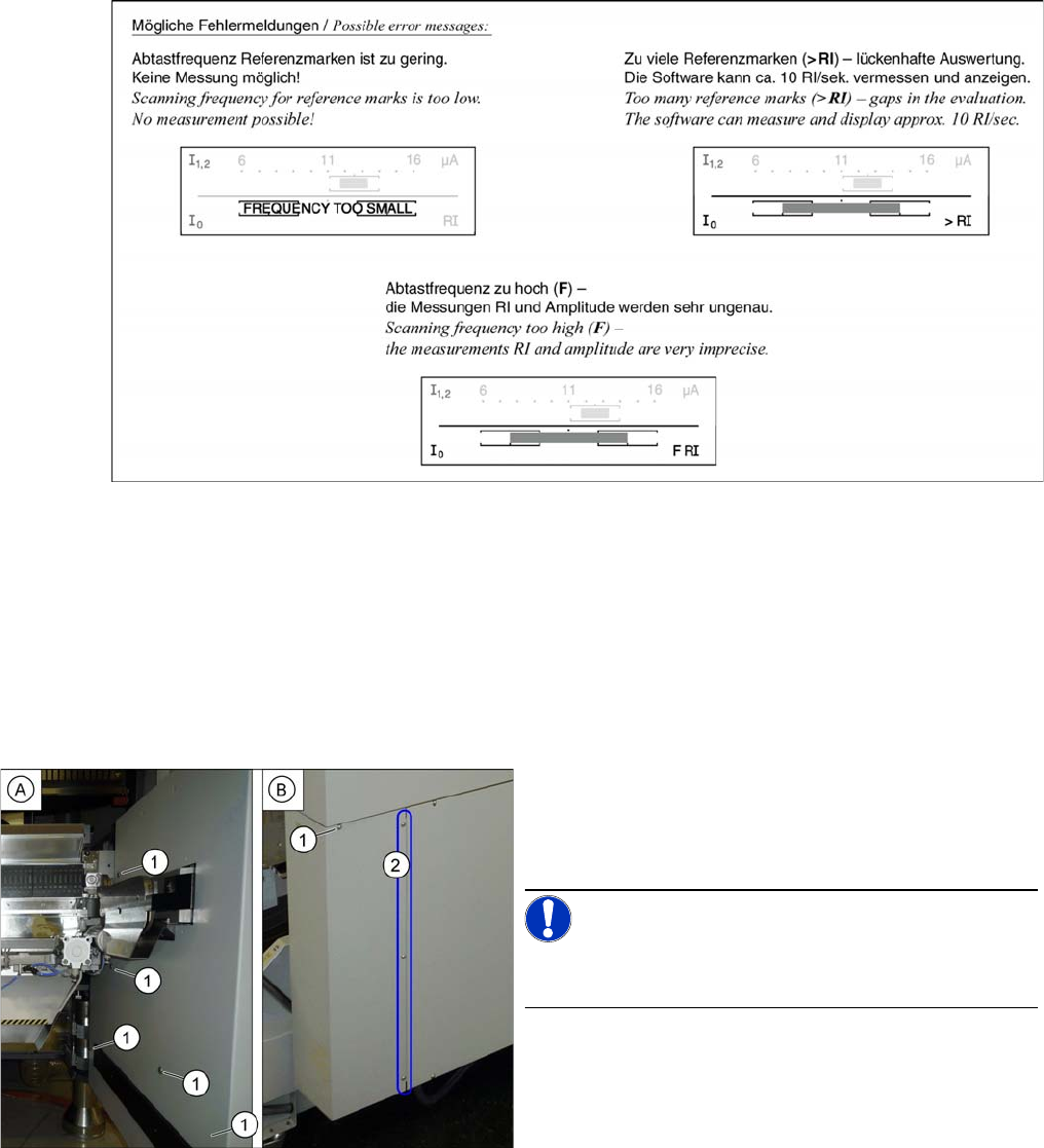
► Loosen the six screws (1) fastening the inside (A)
and outside (B) of the side covers and remove the
side covers. While unscrewing, always hold on to the
side cover, to prevent it falling off.
NOTICE!
The three fastening screws (2) on the outer side are loos-
ened as a default. The side cover can be pulled out here.