00197783-01_AI_Gantry-Retrofit_X-Series_S_INTERNAL_de_en.pdf - 第154页
Appendix Description of Boards 4.2.2 Vision board spread spectrum HCU [03 067289-xx] 154 Gantry Retrofit Portalna chrüstung 4.2.2.1 4 . 2 . 2 . 1 D I P S w it c h o n t h e V is io n B o a r d ( D ig it a l V e r s io n …
Appendix
4.2.2 Vision board spread spectrum HCU [03067289-xx] Description of Boards
Gantry Retrofit Portalnachrüstung 153
4.2.2
4.2.2 Vision board spread spectrum HCU [03067289-xx]
Vision board spread spectrum HCU [03067289-xx]
03067289-02
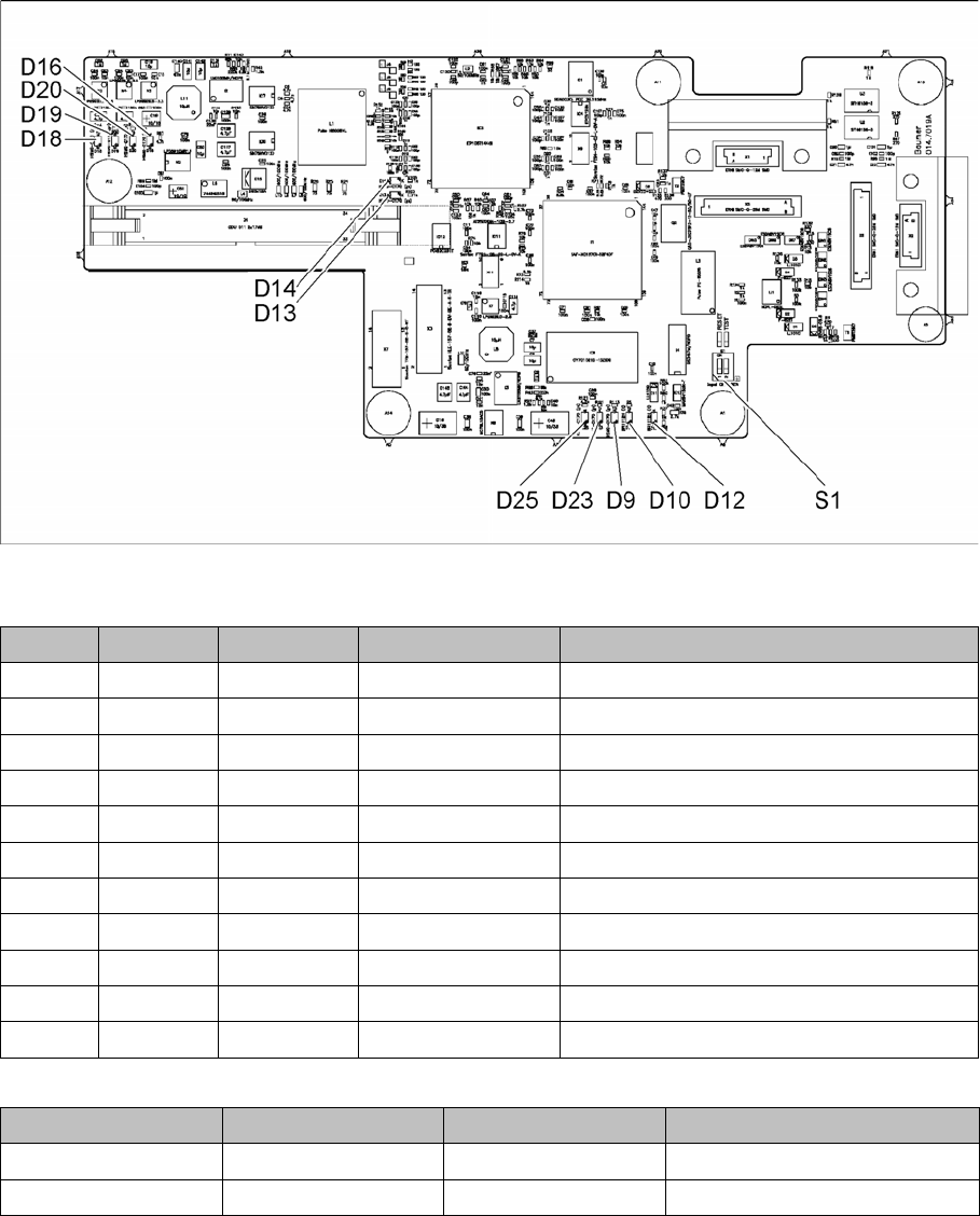
LED [03067289-02]
Dip switch S1 [03067289-02]
LED Color Status Signal name Description
D9 GN ON LED_XC_OK RUN
D10 RD ON LED_XC_ERR ERROR
D12 RD ON XC_RESET RESET
D13 GN ON IO/LVDS51P PCB camera active
D14 GN ON IO/LVDS51N CO camera active
D16 GN ON P12VCAM_I +12VDC for camera
D18 GN ON P5VCAM +5VDC for camera
D19 GN ON P2.5VCAM + 2.5 VDC for camera
D20 GN ON P3.3VCAM + 3.3VDC for camera
D23 GN ON P5V +5VDC
D25 GN ON P15V +15VDC
Switch Status Signal name Description
S1.1 OFF HW_RESET ON: RESET CAN controller
S1.2 OFF CAN_ID Not used

Appendix
Description of Boards 4.2.2 Vision board spread spectrum HCU [03067289-xx]
154 Gantry Retrofit Portalnachrüstung
4.2.2.1
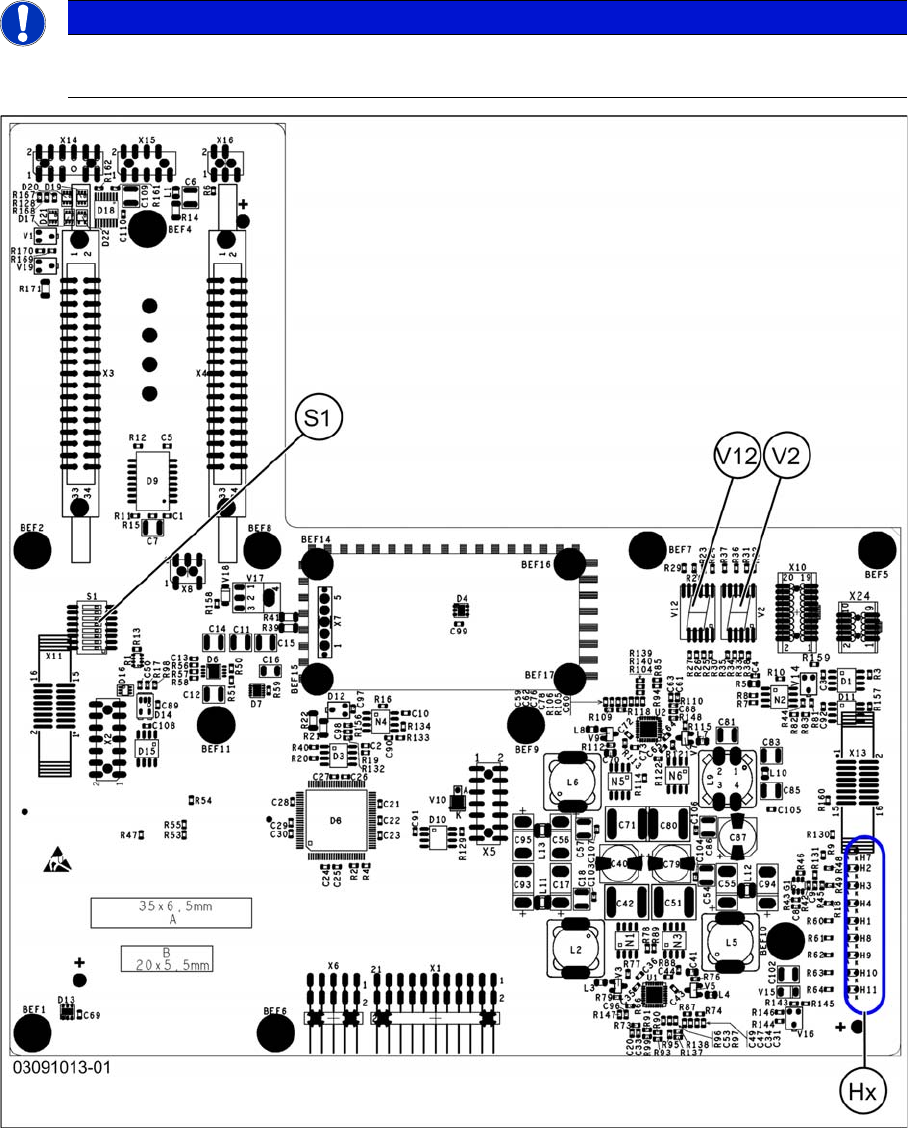
4.2.2.1 DIP Switch on the Vision Board (Digital Version 02)
DIP Switch on the Vision Board (Digital Version 02)
* Not all gantries may be available, depending on the machine type.
S Gantry* Comments
1 2 3 4
1 OFF OFF OFF OFF Reset - CAN processor
2 OFF ON OFF ON PID0 address switch 1 -> gan-
try
3OFF OFF ON ONPID1 address switch 2 -> gan-
try
4 OFF OFF OFF OFF CAN R - switch for the terminal
resistor on the CAN bus
5ON ON ON ONSpeed: ON = 1 Mbit/s, OFF =
500 Kbit/s
6ON ON ON ONCAN ID - for X machine ON
Appendix
4.2.3 Head Interface C700X-L/R HR Description of Boards
Gantry Retrofit Portalnachrüstung 155
4.2.3
4.2.3 Head Interface C700X-L/R HR
Head Interface C700X-L/R HR
There are two head interface designs. Depending on the gantry, either the head interface C700X-L or
C700X-R will be used.
Standard gantry (not rotated) [03091013-01]
NOTICE
C&P20 P
If you are converting to an C&P20 P, the head interface must have at least function state -03.